
| Time duration | September 2016 to December 2016 |
| Location | Malaysia |
| Organization | International Islamic University Malaysia |
| Project | Structural Analysis & Design Office |
| Position |
[CE 2.1]
This career episode relates to project titled “Structural Analysis & Design Office’’. The project was assigned to me as a part of my 4th Year 1st Semester of engineering at International Islamic University Malaysia.
[CE 2.2]
I was required to prepare design report on the following beam, slab and staircases.
[CE 2.4]
The project Hierarchy is given below -

[CE 2.5]
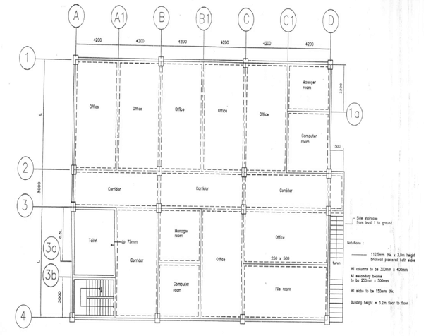
| Office | Ceramic tiles on in-situ reinforced solid slab. Suspended ceiling bellows beams. Lightweight partitions as required to offices. |
| Manager room | Carpets on in-situ reinforced concrete solid slab. Suspended ceiling below beams |
| Corridor | Ceramic tiles on in-situ reinforced concrete solid slab. Suspended ceiling below beams |
| Files room | Cement render on in-situ reinforced concrete slab. No ceiling under. |
| Computer rooms | Carpets on in-situ reinforced concrete solid slab. Suspended ceiling below beams |
| Staircase | Ceramic tiles on in-situ reinforced concrete. Enclosed in 112.5mm x 3.0m height brickwork plastered on both sides. |
| Toilet | Ceramic tiles on in-situ reinforced concrete slab. No ceiling under. All internal walling lightweight partition. Enclosed in 112.5mm x 3.0m height brickwork plastered on both sides. |
| External wall | generally 112.5mm x 3.0m height brickwork plastered on both side. |
| Fire protection | All elements of the construction to have minimum of 1 hour fire resistance. |
[CE 2.6]
I did following calculations
Concrete Unit weight = 25 kN/m2
Brickwall unit weight = 2.6 kN/m2
Brickwall height = 3 m
Concrete render = 0.3 kN/m2
Ceramic tiles = 1 kN/m2
Lightweight partitions = 1 kN/m2
Building Services = 0.3 kN/m2
Ceiling = 0.5 kN/m2
Carpet = 0.05 kN/m2
Primary beam = 250 x 650 mm
Secondary beam = 250 x 500 mm
Slab thickness = 150 mm
Assumed Bars:
Ø bar 1 = 20 mm
Ø bar 2 = 16 mm
Ø link = 6 mm
Imposed Load, Qk
Office = 2.5 kN/m2
Corridor = 3.0 kN.m2
File Room = 5.0 kN/m2
Manager Room = 2.5 kN/m2M
Computer Room = 3.5 kN/m2
Dead Load & Imposed Load for each room:
Office:
Dead Load:
Slab self-weight = 25(0.15) = 3.75 kN/m2
Cement render = 0.30 kN/m2
Ceramic Tiles = 1.0 kN/m2
Lightweight partitions = 1.0 kN/m2
Building Services = 0.3 kN/m2
Ceiling = 0.5 kN/m2
Gk = 6.85 kN/m2
Imposed Load,
Qk = 2.5 kN/m2
[CE 2.7]
I also did calculations for Durability, Fire and Bond requirements
Min, cover with regard to bond cmin, b = 20 mm
Min, cover with regard to durability cmin, dur = 20 mm
Min required axis distance for R60 fire resistance,
asd = 30+10 = 40 mm
Min cover with regard to fire = Cmin = asd - ꬾlink -ꬾbar/2
= 40-6-20/2 = 24mmAllowance in design for deviation, ∆Cdev = 10mm
Nominal cover, Cnom = Cmin + ∆Cdev = 24+10 = 34mm
[CE 2.8]
Beam C/1-2
Ly/Lx = 5800/4200 = 1.38<2 (two-way slab)
Shear Coefficient βv =0.49
Slab Gk = 6.85 kN/m2 (office)
Slab Qk = 2.5 kN/m2 (office)
Beam self-weight = 25(0.65-0.15)x0.25=3.125 kN/m2
Brick weight = 2.6 x 3 = 7.8 kN/m2
Dead load from slab B1-C1/1-2: 2x(0.49)4.2x6.85 = 28.19 kN/m2
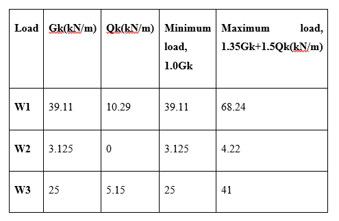
Gk = 28.19 + 3.125 + 7.8 = 39.11 kN/m
Imposed load from slab B1-C1/1-2
= 2x(0.49)4.2(2.5)=10.29kN/m2
Qk = 10.29 kN/m
Total Design load (W1)
W1 = 1.35 Gk + 1.5Qk
W1 = 1.35(39.11) +1.5(10.29) = 68.24 kN/m
Corridor
Slab Gk = 5.85 kN/m2
Slab Qk = 3 kN/m2
Load on beam C/2-3
Beam self-weight = 25(0.65-0.15) x 0.25=3.125 kN/m
Gk 3.125 = 3.125 kN/m2
Qk = 0 kN/m2
(Qk=0 because it is one-way and has no effects on beam C/2-3)
W2 = 1.35 (3.125) + 1.5(0)= 4.22 kN/m
I ignored the slab weight because it has no effects on the beam.
[CE 2.9]
I did Uniform load setup as following
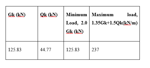
Uniform load (W)
Point load (P)
[CE 2.10]
I did effective flange width as following
beff = ∑beff I + bw < b
beff I = 0.2bi + 0.1l0 < 0.2l0
Span C/1-2
bw = 250mm
hf = 150mm
h = 650mm
b1 = 1975 mm
b2 = 1975 mm
Actual flange width, b = b1 + b2 + bw = 1975+1975+250 = 4200mm
beff = ∑beff I + bw < b
beff I = 0.2bi + 0.1l0 < 0.2l0
l0 = 0.85l = 0.85 x 5800 = 4930 mm
beff 1 = 888 mm < 986 mm Use: 888 mm
beff 2 = 888 mm < 986 mm Use: 888mm
beff = 888 + 888 + 250 = 2026 mm < 4200mm
Span C/2-3
l0 = 0.7l = 0.7 x 3000 = 2100 mm
b1 = 1975 mm
b2 = 1975 mm
beff 1 = 605 mm > 420 mm Use: 420 mm
beff 2 = 605 mm > 420 mm Use: 420 mm
beff = 420 + 420 + 250 = 1090 mm < 4200mm
Span C/3-4
bw = 250mm
hf = 150mm
h = 650mm
b1 = 1975 mm
b2 = 4075 mm
Actual flange width, b = b1 + b2 + bw = 1975+4075+250 = 6300 mm
beff = ∑beff I + bw < b
beff I = 0.2bi + 0.1l0 < 0.2l0
l0 = 0.85l = 0.85 x 5800 = 4930 mm
beff 1 = 888 mm < 986 mm Use: 888 mm
beff 2 = 1308 mm > 986 mm Use: 986 mm
beff = 888 + 986 + 250 = 2124 mm < 6300 mm
[CE 2.11]
Main reinforcement was calculated as below
Span C/1-2
Effective depth (d) = h-Cnom - Ø link -1.5 Ø bar = 650-35-6-1.5x20 = 579 mm
Bending moment,
M = 216 KN.m
Mf = 0.565 Fck b hf (d-0.5hf) = 0.565 x 25 x 2026 x 150 x (579-0.5x150) = 2163.5 KN.m
M < Mf (Neutral axis is in the flange)
K = M /fckbd2 = 216x106 / (25x2026x5792) = 0.013
Z = d[0.5 + √(2& 0.25-k/(1.134 ) )] = 579 [0.5 + √(2& 0.25-0.013/(1.134 ) )] = 572.8 mm
As = M / 0.87Fyk Z = 216x106 /0.87x500 x 572.8
= 866 mm2
Minimum and Maximum reinforcement area:
As,min = 0.0013bd
0.0013bd = 0.0013x250x579 = 188.17 mm2
As,max = 0.04bh = 0.04x250x650 = 6500 mm2
[CE 2.12]
Slab Design
Assumptions
Ø bar = 10 mm
Concrete Unit weight = 25 kN/m2
Concrete render = 0.3 kN/m2
Materials:
Unit weight of concrete = 25 KN/m3
Characteristic strength of concrete, Fck = 25 KN/m2
Characteristic strength of steel, Fyk = 500 KN/m2
Primary beam = 250 x 650 mm
Secondary beam = 250 x 500 mm
Slab thickness = 150 mm
Slab thickness = 150 mm
Durability, Fire and Bond requirements
Min, cover with regard to bond cmin, b = 10 mm
Min, cover with regard to durability cmin, dur = 15 mm
Min required axis distance for R60 fire resistance,
a = 20 mm
Min cover with regard to fire = Cmin = a -0.5 Ø bar = 20-10/2 = 15 mm
Allowance in design for deviation, ∆Cdev = 10mm
Nominal cover, Cnom = Cmin + ∆Cdev = 15+10 = 25 mm
[CE 2.13]
I did shear force calculations as following
Two-way restrained slab
B1-C/1-2, C-C1/1-2, B1-C/3-4 (Office)
Long span Ly = 5800 mm
Short span Lx = 4200 mm
y / Lx = 1.4 < 2.0 (Two-way slab)
Case 2: One short edge discontinuous
Short Span:
Vsx1 = βsx1 nd Lx = (0.45) (13) (4.2) = 24.57 KN
Vsx2 = βsx2 nd Lx = (0.45) (13) (4.2) = 24.57 KN
Long Span:
Vsy1 = βsy1 nd Lx = (0.36) (13) (4.2)= 19.66 KN
Vsy2 = βsy2 nd Lx = (0.24) (13) (4.2) = 13.10KN
Design force VEd = 24.57 KN
Design shear resistance,
VRd,c = [0.12k(100 ρ 1Fck )1/3]bd
K = 1+ (200/d)1/2 < 2.0
K = 1+ (200/120)1/2 < 2.0
2.29>2.0 use 2.0
ρ 1 = As1/bd < 0.02
ρ 1 = 314/1000x120 < 0.02 = 0.003<0.02
VRd,c = [0.12x2(100 x0.003x25 )1/3]1000x120
= 56374 N = 56.4 KN
Vmin = [ 0.035K3/2 Fck1/2] bd
= 0.035 x 23/2 x 250.5 x 1000 x 120 = 59.4 KN
So, VRd,c = 56.4 KN > VEd
[CE 2.14]
I completed the project report efficiently and within the stipulated time. I did all the management of the project and calculated multiple aspects of the project very well. In case of any issues I always contacted my project supervisor. I also consulted internet resources and library for resolving the calculation issues.