
[CE 2.1] This project was completed in my Masters at RMIT University, Australia. “Wireless Power Transmission” was the title of the project.
| Title of Project | Wireless Power Transmission |
| Date | March 2016 – November 2016 |
| Location | RMIT University, Australia |
| Position | Electrical Engineering Student |
[CE 2.2] Recent advancements have been introduced in the technology sector which includes mobile phones, tablets, and laptop. The demand for power increases results in the features complexity. The mobile devices energy demand management is increasing rapidly and it brought up the wireless charging concepts with the wireless energy transfer. Wireless power was of two types which include near-field wireless power and far-field wireless power. Capacitive coupling is the technique which has its own applications and it utilizes an electrical field to electricity transfer. Through coils to transfer electricity with the magnetic resonances and inductive coupling was utilized for the electricity transfer related to the magnetic field.
[CE 2.3] I implemented the wireless power transmission and it was completed by splitting it into numerous milestones which were executed within the project deadline.
[CE 2.4] The project nature was related to implementing and testing the wireless power transmission. I included the protection circuit in the whole design which was mainly for minimizing the risk associated by isolating the circuit in case of any fault.
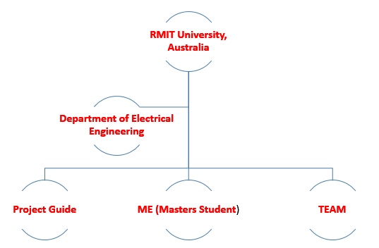
[CE 2.5] My position is shown in the below organogram:
[CE 2.7] The development of wireless power transfer was targeted mainly for the charging of mobile applications including tablets and mobile applications. Moreover, I also conducted in-depth research on the wider market prospects of the developed wireless power transfer concepts and it was required for making the project successful in the long run.
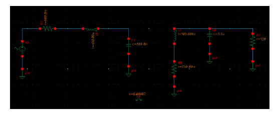
[CE 2.8] I initiated the project by conducting the simulations using CADENCE software. In the circuit built, I connected the transmitter to the outlet socket which was then connected with the wall for the magnetic flux generation. I used air coils in the transmitter circuit for performing this operation. In the operation, the magnetic fluxes moved to the upward and linked it to the circuit at the receiving end. I used DC power for the load. I maintained the distance between the primary and receiving end of the circuit.
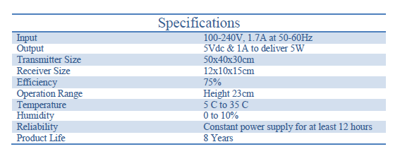
[CE 2.9] I provided the input power signal to the transmitter which was 100-240V, 2A at 50Hz. I obtained the output of 20Vdc and 4A for delivering the 60W power to the laptop. I set the output specifications within the operating range and the needed power was delivered with the 75% efficiency. I implemented the mini-prototype which was developed for testing the desired performance. I assembled the main product and it was tested against the performance needs. I ensured that it just work properly. I did testing which was achieved with the desired outcome. I operated the device connected with the wireless electricity circuit. I operated it within the specified range. I placed the object between the receiver circuit and the transmitter circuit. I worked on selecting the appropriate components and the product specifications obtained is shown below.
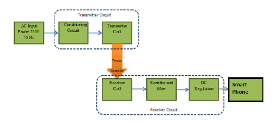
[CE 2.10] I implemented the conditioning circuit which was required for generating the resonant frequency at 8 kHz. I then amplified the input signal current for the purpose of generating more fluxes. I used a signal generator which was the main element in the circuit conditioning and it was followed with the audio amplifier for amplifying the overall signal strength. The overall system block diagram is shown below:
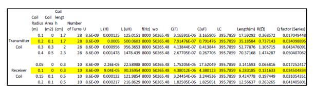
[CE 2.11] With the transmitting circuit, I connected the LED at the receiving end. I worked on making the number of turns in the coil and it was needed to achieve turned 24 turns. I directly obtained the relation between the transmitting and receiving coils at the significant distance which was required among the two coils. I also noted that the current design had few limitations which I took into consideration when working on the actual circuit. I did the calculations for the transmitter and receiving coils as shown below.
[CE 2.12] In this step, I worked on the prototype development which was for the power transmission wirelessly. I used a single coil circuit on the receiving side which was designed to quickly test the concept, and an LED was used as a DC load. I successfully tested the power transmission between the receiver and transmitter to identify the range of operation of the whole system.
[CE 2.13] I implemented the bridge rectifier in the design which was for the purpose of converting the AC voltage into DC voltage. I recorded the maximum of 13.5 V DC at the output. I selected the rectifier which was particularly supported the reverse voltage with the range from 20V to 100V. I fed the 5V voltage to the linear regulator for the purpose of charging the smartphone. I added a linear regulator for avoiding the overheating of the smartphone from the charging. I selected the linear regulator with the current range of 1A.
[CE 2.14] With the current design, there were various drawbacks which I took into consideration. Firstly, the transistor seemed to overheat during the experiment, which was due to the high amount of current being drawn and I added the heat sink in the design. I did more research about the transistor for higher performance. Secondly, the operational range seemed to be too short, which was more likely due to the number of turns in each coil. I solved this issue by conducting the calculations related to the number of turns in both the primary and secondary side. The calculations can be checked in the above figure.
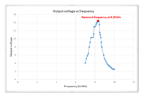
[CE 2.15] I tested the system performance which was based on the simulation results and improved the design operational range. I varied the frequency using the function generator. I set it at 10 kHz. I obtained the resonance phenomena from the voltage and it reached to the maximum when the output voltage was 14.5V. I obtained the graph as shown below which illustrated the relationship between the output voltage and frequency.
[CE 2.16] I completed the transmitter design and noted that there was the overheating in the design occurred because of the experiment. It was because of the current being drawn in a higher amount. I included the heat sink and obtained the transistor which provided higher performance and long durability. I enhanced the system performance which was employed for powering the amplifier. I increased the transmitter's magnetic flux. I noted a few losses in the prototype design from the simulation. I recommended to had further research in this domain. I obtained the simulation results for the receiving circuit (receiver) as well. My Electrical Engineering skills were gradually increased while working on this project of wireless power transmission.
To read more.............. Kindly check the below links.
We hold the apex position in providing services regarding CDR writing for engineers Australia. We are known to have very high success records for consistent team of professional writers having years of experience in the field of CDR preparation. We provide the best and trusted service for CDR writing and reviewing of all kinds of engineering disciplines. We provide services for career episode writing, plagiarism check and removal etc.
Should you need any further information, please do not hesitate to contact us.
Contact: +61-4-8885-8110
WhatsApp: +61-4-8885-8110
(Australia, USA, UK, UAE, Singapore, New Zealand)