
[CE 3.1]
I completed this project “Automated Finite Element Model Development & Analysis of Single Phase Three Limb Transformer” at RMIT University, Australia.
| Project Title | Automated Finite Element Model Development & Analysis of Single Phase Three Limb Transformer |
| Project Duration | 15th August, 2018 – 15th October, 2018 |
| Location | RMIT University, Australia |
| Position | Electrical Engineering Student |
[CE 3.2]
I did the designing of the limb transformer which was single phase with certain parameters utilizing LUA coding and it was done in FEMM software. I obtained various results and then analyzed them accordingly. I designed the model which was for the specific model in the project. I also noted few drawbacks related to the code. The code was complex but the results obtained were correct. The code length was high and I obtained the geometry with the assistance of the coded file. I completed the finite element analysis for the design and code was applied in such a way that the proposed design was tested to save human effort and time.
[CE 3.3]
The project aim was based on deducing the human effort and save time when working on the transformer design. I worked on the coded file for avoiding the design of every single model. I made alterations related to the voltage ratio, turns ratio, material utilized for the model designs. I did not gain the geometry with the results. For single model, I implemented the finite element analysis and results were based on the coded file. I designed the program which assisted in completing the experiments and made alterations in the single coded file.
[CE 3.4]
The project nature was the automated finite element model development and it was even based on the three limb single phase transformer and I worked on it efficiently to obtain the required project objectives.
[CE 3.5]
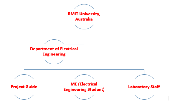
Below organogram shows my project position -
[CE 3.6]
These were my main duties -
[CE 3.7]
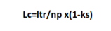
I initiated the project with the shell type transformer geometric model and it was formulated with the transformer insulation thickness and length together with the factors which defined the whole geometry. I specified the proportion factor among the transformer various parts. In the magnetic core, there was the leg length which was expressed utilizing the slot length and the length was required in terms of forming the pole of electromagnetic nature. I set the number of poles at 2 which was for the single-phase transformer and it was then used in the equation below.
[CE 3.8]
I utilized the MATLAB for the implementation of the link FEMM software with the assistance of the octave FEMM coding. I automatically installed the Octave FEMM in the mfiles subdirectory. I selected the typical directory which was c:\Program Files\FEMM42\mfiles. I added the required path to use FEMM with MATLAB and it was included in the program’s search window. I then added this path with the search path and it was followed with the lines at the command prompt of MATLAB.
[CE 3.9]
I selected the transformer size which was related to the electromagnetic devices power and it allowed the density flow which included flux density, current density and the density loss. I increased the loading for decreasing the transformer size. I set the parameters as per the related power loss generation and it resulted in the heat dissipation. I selected the magnetic coupling between the windings which were based on the core flux and it was linked with each winding turn. ideal transformer the magnetic coupling between the windings is perfect. I obtained different sizes and specifications for checking the designed model suitability. I investigated the shell-type transformers and it was needed for checking the maximum flow in the electric and magnetic circuit cross-sectional area. I expressed the volume based on size along with the power transparent and the densities electromagnetic flow. I checked the transformer parts and it was based on the heat losses and the transfer. I also checked the power and the voltage drop for checking the overall transformer weight.
[CE 3.10]
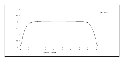
I worked on the slot length for the windings and it was based on the formulation as per the length of the electromagnetic pole and the slot length relative area. At various intervals, I obtained the magnetic field as shown in the below graph.
[CE 3.11]
I did the geometry design on FEMM and it was based on the rules and formula. I equalized the weight WTR and base LTR. I set the least possible value for the gap among the coils. I obtained the L.C of 0.5 for the first and third leg and I selected the LS based on the window length. However, I selected WS based on the height. I kept it same for both the windows along with the L.C. I implemented the central limb based on the LC. I set up the window configuration along with the low voltage winding with the central limb. I covered the low voltage winding with the high voltage winding.
[CE 3.12]
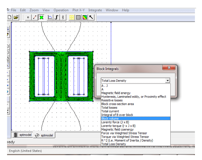
I completed the conductor selection and it was based on various factors based on the current rating. I set 3A as the current value and then checked the AWG rating from the data sheet which was based on the data sheet. I decreased the AWG value as it was required with the conductor size selection. I noted the voltage drop for the 22AWG which was 90volts. I also worked on the flux linkage and it is shown in the below graph.
[CE 3.13]
There were few challenges which I faced while implementing the program on MATLAB. It was difficult in terms of linking the MATLAB with FEMM directory. In FEMM, I linked and fed both directions which was difficult. I conducted research on the geometric design which was as per the geometry design according to the parameters. I selected the core material along with the winding for the wire gauge as per the ratings. I designed model for coding which was at the time of implementation.
[CE 3.14]
I completed the experiment which was for different geometries and specifications. I concluded that the code file resulted in reducing the human effort for selecting the transformer with the suitable and optimum ratings. I altered the specification along with the geometry until the flux linkage met with the voltage drop and density. It resulted in obtaining the power. The system did not only result in reducing the human efforts but also became economical. The manufacturing cost was related to the transformer weight. I also showed the weight calculation formula and the user was response for selecting the model to note the device weight. I completed the single phase three limb transformer finite element analysis which provided the detailed analysis and it resulted in strengthening my Electrical Engineering skills.
To read more.............. Kindly check the below links.
We hold the apex position in providing services regarding CDR writing for engineers Australia. We are known to have very high success records for consistent team of professional writers having years of experience in the field of CDR preparation. We provide the best and trusted service for CDR writing and reviewing of all kinds of engineering disciplines. We provide services for career episode writing, plagiarism check and removal etc.
Should you need any further information, please do not hesitate to contact us.
Contact: +61-4-8885-8110
WhatsApp: +61-4-8885-8110
(Australia, USA, UK, UAE, Singapore, New Zealand)