
| Time duration | |
| Location | |
| Organization | |
| Project | Radio Frequency Implementation for Speed Control of Vehicle |
| Position | Structural Design Engineer |
| Project Supervisor | |
| Project submitted to |
This career episode is allied with my project titled “Radio Frequency Implementation for Speed Control of Vehicle”. This project was carried out and submitted for Bachelor degree requirement in Electronics & Communication Engineering.
[CE 1.1]
I undertook this project in _______year as part of my undergraduate degree in Electronics & Communication Engineering requirement. I executed this project in a group of three engineers including me.
[CE 1.2]
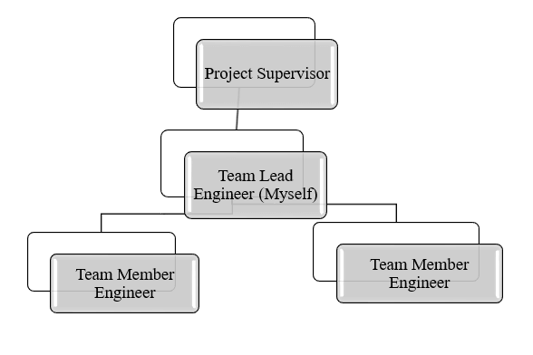
It is quite common globally for the Engineers to carry out certain projects during their academic period. I was enthralled when I went through the project topics from my project supervisor. I was quite happy to take project related to the RF communication. The topic really fascinated me and I took this project as a challenge and completed in a group of three Engineers including myself. I was also given the role of Teal lead for this project by my project supervisor.
[CE 1.3]
I organized this project grounded on the Radio Frequency & Embedded expertise. The project was chiefly implied for controlling the speed of the vehicle primarily following the received signals from the corresponding transmitting body.
[CE 1.4]
I went through numerous offline & online sources to get information about the RF & Embedded technologies. I studied the topic in detail in order to execute the project accordingly. I also had numerous meetings with the project supervisor in order to have in depth knowledge and resolve any issues related to the project. I also documented the complete project as per requirements.
The project Hierarchy is given below -
[CE 1.5]
I defined the basic key components of the project as following -
[CE 1.6]
I grounded the entire project on Radio frequency & Embedded system. When the Car enters a restricted area the signal was read by the Receiver & was correspondingly transmitted by the Transmitter previously situated in the restricted area. The signal thus received was later decoded by the micro-controller & make the driver of the Car on high-alert through Liquid Crystal Display (LCD). Depending upon the signal the micro-controller plays its part by limiting the speed of the DC-motor which in turn lessen the speed of the vehicle.
[CE 1.7]
As a lead Engineer I first presented the methodology of the system along with block diagram & schematic diagram of the whole project as shown below.
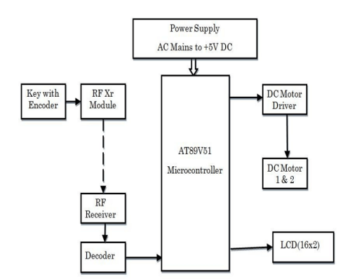
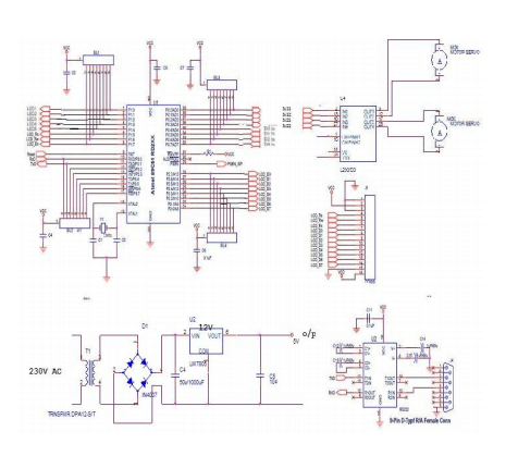
[CE 1.8]
I designed the complete electronics of the power supply. The power supply was incorporated with a stepdown transformer, full bridge rectifier and a Regulator IC for providing proper DC5V to the system circuit. The block diagram & circuit diagram of power supply unit is given below. It was entirely my work of art.
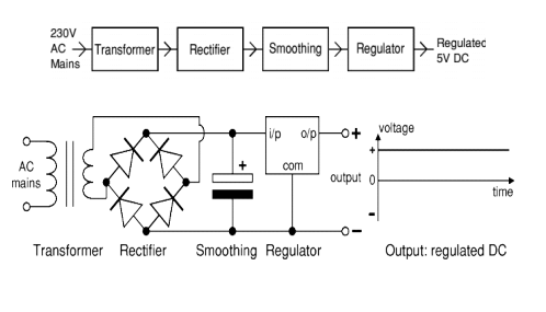
I used full bridge rectifier in order to completely convert AC supply in to pure DC supply. For the purpose of delivering clean 5VDC I used 7805 Voltage Regulating IC. While testing of the power supply I saw that the voltage regulator was getting way hotter than the limits according to its datasheet. I worked on decreasing the heat and found a solution in the form of heat sink. I attached the shaped heat sink with the body of regulator. This solved the issue of overheating and brought the temperature of the regulator equivalent to the ambient temperature.
[CE 1.9]
I searched a lot to find the most efficient yet cost effective microcontroller. I went for 89C51 micro-controller made by A.T.M.E.L Company. I chose this micro-controller because of its 33MHz speed, extendable R.A.M to 64K.B.s, four X 8-bit inputs & output ports and last but not the least due to 128 Bytes of internal memory. I studied all of its pins through the datasheet and drafted a schematic for its flawless connections. The most difficult task was connecting the LCD with the microcontroller. I worked hard in this aspect and studied the LCD and micro-controller pin-outs for seamlessly connecting both the prime components. My approach toward the LCD & microcontroller connection worked fine and the LCD displayed all the required parameters without any fail.
[CE 1.10]
I implied a serial-communication technique for synchronizing with the microcontroller and the entire system to be controller. It’s the most common and extra reliable technique for communication amid microcontroller and the system. Since RS-232 was not directly attuned with micro-controller I used an integrated circuit M.A.X.X 232 for this operation. It had a 16 pin topology. The function of this IC was to convert the Rs-232 signals in to T.T.L voltage echelons. I implied S.B.U.F 8 bit register for performing the serial communication among 89C51 micro-controller.
[CE 1.11]
For performing the Radio Frequency based communication I designed the Transmitter & Receiver as following.
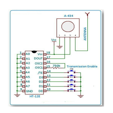
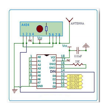
[CE 1.12]
I used L.293.D driver IC in order to connect the DC motor with the 89C51 micro-controller. In this project I implied two DC-motors i.e. one for front control & one for rear control of the Vehicle. Below figure clearly shows the interfacing where the pic # two & seven of the IC are the in-puts from the 89C51 microcontroller and pic# three & six of the L.293.D IC are the inputs to the DC-motor.
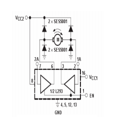
[CE 1.13]
I used Keil Software for the coding of the microcontroller. It’s the best software for all kind of simulations and executions.
Some of the example codes written are given below -
#include
#include
#include
#include ‘’lcd.h’’
#define_motor1Cnt1 P0_0
#define_motor1Cnt2 P0_1
#define_motor2Cnt1 P0_2
#define_motor2Cnt2 P0_3
Void_forward1_Handle(void);
Void_forward2_Handle(void);
Void_forward3_Handle(void);
[CE 1.14]
I was also accountable for the feasibility study of the project. I also drafted the reports of the project progress. I passably kept the supervisor informed of all the stages of the project. My project management skills were highly endorsed by the project supervisor.
[CE 1.15]
The venture was strongly planned and model was simulated & constructed. I altogether checked the employability of venture. The task helped me in building up my insight with respect to RF communication and uncovered my aptitude in the outline of such frameworks at a more extensive level. This undertaking raised my venture administration, arranging, examination and execution abilities. The framework was effectively reproduced and was profoundly respected by the Project Supervisor.
We hold the apex position in providing services regarding CDR writing for engineers Australia. We are known to have very high success records for consistent team of professional writers having years of experience in the field of CDR preparation. We provide the best and trusted service for CDR writing and reviewing of all kinds of engineering disciplines. We provide services for career episode writing, plagiarism check and removal etc.
Should you need any further information, please do not hesitate to contact us.
Contact: +61-4-8885-8110
WhatsApp: +61-4-8885-8110
(Australia, USA, UK, UAE, Singapore, New Zealand)