| Time duration | |
| Location | Saudi Arabia |
| Organization | General Electric (www.gepower.com) |
| Project | Restoration of GE 7FA-03 Gas Turbine after Compressor Wreck |
| Position |
[CE 3.1]
I joined GE in a Services Leadership Program which was designed to train experienced new hires about GE’s design, operation and financial processes on fast track basis. I had the opportunity to learn and get hands-on experience of maintenance and troubleshooting of several Industrial Gas Turbine ranging from 50MW to 180MW. After completing my one year on job training, I was assigned as Lead Contract Performance Manager to a multi-million dollar long-term maintenance contract with one of prestigious customer i.e. ENGIE. After my hiring I was responsible for preparing computerized maintenance plans, budgeting, coordinating to resolve all technical and contractual issues, executing planned & unplanned outages of assigned power plants. I was also responsible for availability and reliability guarantees of the plants.
[CE 3.2]
My assigned Power Plant was having 9 x GE Frame 7FA.03 & 2 x 7EA Gas Turbines with the total capacity of 1800 MW. On January 5 2016 my M&D informed me that there wa sudden increase in vibration and decrease in compressor discharge pressure (CPD) in one of the 7FA.03 unit installed at Juaymah site. I immediately arranged borescope inspection and found that unit was completed wrecked. It was catastrophic failure which damaged complete compressor rotor, stators, casing and some of turbine components. As contract & site owner I was responsible for execution of this major outage.
[CE 3.3]
My most critical tasks in this job were:
[CE 3.4]
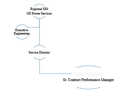
The project Hierarchy is given below. I was responsible to identify scope of work, identify and arrange required resources and parts, execute the job and resolve all technical and administrative hurdles till completion of project.
[CE 3.5]
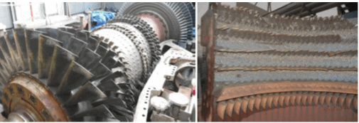
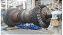
Damaged Assessment: After disassembly I started the project by conducting detailed inspection for making damage assessment of all the compressor rotor & stator vanes. The Mid Compressor Casing (MCC) was also damaged. Pictures of damaged rotor and stator vanes are given below.
[CE 3.6]
In addition to rotor/stator, I performed damaged mapping on MCC as well. Following were my comments after damage assessment and structural analyses of casing:
On above grounds, I recommended to the customer that complete casing was also required to be replaced in addition to rotor and stator vanes.
[CE 3.7]
As part of GE’s field quality management procedure I developed Quality control plan (QCP) for this project. Emphasis was given on critical hold & witness’s points. I identified all the check points and incorporated into the QCP. I mentioned the relevant drawing, clearance diagram and applicable field procedure reference as verification document for each inspection points. The QC\P was submitted to customer for review and approval, which was approved later.
[CE 3.8]
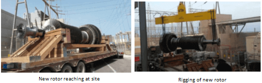
All the upper halves of casings (inlet, CDC, MCC, turbine & exhaust) were removed. After taking opening clearances, rotor was required to be rigged and removed. It was complex and important rigging having rotor weight of more than 50Ton; I designed a lifting plan keeping in consideration the center of gravity. Crane position, boom length, slings and lifting beam were key factors of lifting plan. The lifting plan was approved and rotor was safely removed and placed on rotor stands.
[CE 3.9]
After rotor removal, MCC casing, lower half compressor vanes and lower half turbine hot gas components were removed including Stage-1, 2, 3 Buckets, nozzles and shrouds. Combustion parts (Caps, lines, Transition pieces & fuel nozzles) were also removed. Detailed inspections of all the components were carried out including visual inspections, measurements, NDT and borescope inspections (where required). After thorough cleaning of lower halves of the casings, assembly of the components was started.
[CE 3.10]
IGVs blades and gears were replaced with new ones. The existing Y&F type IGV actuator was replaced with Woodward type. The new actuator was provided to accommodate any future changes to opening and closing angles of IGVs. With the new actuator the IGV operating angle was 21 degrees (fully closed) to 92.5 degrees (fully open).
[CE 3.11]
Compressor / Turbine Rotor was replaced with refurbished rotor on back buy deal with damaged rotor, the refurbishment was performed in GE Manufacturing facility Dammam Saudi Arabia (GEMTEC). The rotor had R0 blades with enhanced features of airfoil tuning, laser shock peening and dovetail undercuts.
[CE 3.12]
Because of the compressor event the compressor blades and vanes of all the stages from S1 were severely damaged and broken. Stator vanes S14 to 17 and EGVs were removed. Compressor vanes S0 to S13 were not removed as the Mid Compressor Casing was replaced. All the stator vanes were replaced. S0 to S5 stator vanes were replaced as part of Enhanced Compressor Package-3 under FMI # F6135G18. The vane drops were adjusted to specs by machining the vanes base. Shim pinning was performed on two vanes of stage 14 to maintain vane drop limits. Since the allowable limit on individual vane base was only 10 mils, many vanes (391) had to be machined to set vane drops. Machining was done in a local workshop (Al Najim Saudi Int'l Co Ltd) in Dammam.
[CE 3.13]
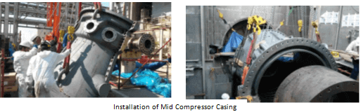
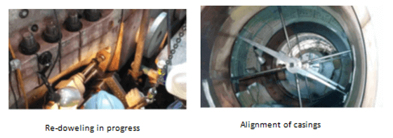
As mentioned above Mid Compressor casing (MCC) suffered heavy dents and damages which were not repairable. MCC was replaced with new one. Prior to installing new MCC, bushings were installed on the dowel holes locations on inlet casing vertical joint (9 places). The purpose was to use the standard size dowel pins after casings alignment.
[CE 3.14]
Dents and rubs were found on Compressor Discharge Casing (CDC). High spots were removed and grinding / polishing was performed. Damaged mapping was done and the dents were found in acceptable limits. NDT (Fluorescent Penetrant Inspection) was performed on hook fit areas, no crack indication was found. CDC was returned to service.
[CE 3.15]
[CE 3.16]
The combustion liners, liner caps and flow sleeves were found in good condition and were reused. The Transition Pieces and fuel nozzles were replaced.
Some of the 1st stage buckets were found with missing material. 2nd stage buckets were found with cooling holes blocked. No significant damage was observed on 3rd stage buckets. Buckets of all the 3 stages were replaced. 1st, 2nd and 3rd stage nozzles were found with metal splatter. 1st stage shrouds found with FOD and rubbing. 2nd stage shrouds found with honeycomb seals worn and damaged. Metal splatter was also found. Minor rubbing was found on 3rd stage shrouds. All nozzles and shrouds were replaced for next operation cycle. Removed nozzles and shrouds were sent to GEMTEC for repair.
No damage was found on Exhaust frame casing. The struts were found in good condition with no cracks.
[CE 3.17]
Moderate scoring was found on turbine bearings and thrust pads. The bearings were replaced with new ones. Thrust bearing cage was also replaced, new active and inactive thrust pads were used. All as-removed bearings were sent to GMETE for re-babbiting. Bearing instrumentation including bearing thermocouples and vibration probes (except bearing-1 axial probes) were replaced. Bearings seals of all three bearings were replaced.
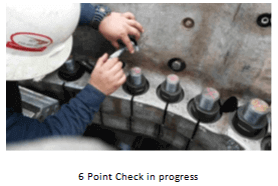
Turbine axial clearances measurement requires the rotor to be set at A-Set Dim with rotor pushed towards active side (exhaust end). While attempting to set the rotor at A-Set Dim by machining of active side thrust shim, it was found varying with temperature. The A-Set Dim was measured in the morning time and active thrust shim thickness was recalculated. Finally A-Set design dimension was achieved and clearances were measured. Compressor and turbine clearances were measured & recorded per new clearance drawing 104T9941 in FMI, all found within specs. Clearances were sent to design team for review and were approved. After installing all the upper half casings, the rotor 6-point check was performed for rotor position and all clearances were found within specs. Inactive thrust shim was machined and Rotor thrust float was set at 10 mils.
[CE 3.18]
During the last MI new alignment specs 334A1553 were followed for Generator to Turbine alignment. Customer reported that new specs caused increase in bearing-1 and 2 temperatures by 10-12 deg C. Therefore, optimized alignment specs between the new and old (363A5495) specs were used during this outage. After generator to turbine alignment, turning gear to Generator alignment was also performed.
Since turbine rotor was replaced, Green Rotor Procedure was followed for unit start up. Unit was cranked on 12 March 2016 and monitored, then reached FSNL. Over speed Trip was also performed. When unit was shut down to restart, the Inlet bleed Heat (IBH) valve was found stuck. The valve was removed by customer and some debris was found stuck in the valve strainer. The valve was replaced with new one by customer.
Unit was successfully started on 14 March 2016 and reached base load. Unit was also tuned. All operating parameters were found normal. Unit was handed over to customer on 14 March 2016.
[CE 3.19]
As this job was having quite big scope of work so there are many other details available however due to space limitation I tried to brief the work I performed. Certainly, this job enhanced my engineering and managerial skills. Starting from getting prepared for this emergent and unplanned job, damage analyses and decision making to execution of the job within quite stretched timeline following complex engineering standards and procedure was amazing opportunity to learn. In addition to technical aspects; this project fine-tuned my project management skills as well.
To read complete CDR.............. Kindly check the below links.
We hold the apex position in providing services regarding CDR writing for engineers Australia. We are known to have very high success records for consistent team of professional writers having years of experience in the field of CDR preparation. We provide the best and trusted service for CDR writing and reviewing of all kinds of engineering disciplines. We provide services for career episode writing, plagiarism check and removal etc.
Should you need any further information, please do not hesitate to contact us.
Contact: +61-4-8885-8110
WhatsApp: +61-4-8885-8110
(Australia, USA, UK, UAE, Singapore, New Zealand)