
| Time duration | |
| Location | Saudi Arabia |
| Organization | General Electric (www.gepower.com) |
| Project | Gas Turbine Efficiency Improvement by Increase in Inlet Guide Vane (IGV) Angle |
| Position |
[CE 1.1]
I joined GE in a Services Leadership Program which was designed to train experienced new hires about GE’s design, operation and financial processes on fast track basis. I had the opportunity to learn and get hands-on experience of maintenance and troubleshooting of several Industrial Gas Turbine ranging from 50MW to 180MW. After completing my one year on job training, I was assigned as Lead Contract Performance Manager to a multi-million dollar long-term maintenance contract with one of prestigious customer i.e. ENGIE. After my hiring I was responsible for preparing computerized maintenance plans, budgeting, coordinating to resolve all technical and contractual issues, executing planned & unplanned outages of assigned power plants. I was also responsible for availability and reliability guarantees of the plants.
[CE 1.2]
My assigned Power Plant was having 9 x GE Frame 7FA.03 & 2 x 7EA Gas Turbines with the total capacity of 1800 MW. After completing last major inspection and implementing Enhanced Compressor upgrade Package on 2 turbines I noticed that although both machines were on baseload but power output of one unit was less by 5MW than the sister unit. Upon further troubleshooting I found that IGV angle of one machine was 84 degree however other unit was operating at 87 degrees and thus giving more output. Therefore, I decided to increase the angle to get equally higher output. In fact, later this project was implemented on all 6 machines.
[CE 1.3]
Upon further analyses I found that the change was not simple. Effect of IGV angle change can lead to some operational issues while running the machine. I was given the task by my manager to carry out a detailed study of this project and bring best possible solution.
The pre-upgrade unit configuration were -
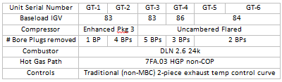
[CE 1.4]
The project Hierarchy is given below -
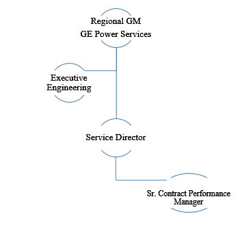
[CE 1.5]
The first critical phase was to make design calculation and simulate different operational scenarios of turbine modes to see the effect of IGV angle change on machine.
Below was the basic information on which study was based:
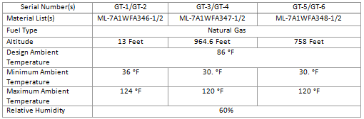
[CE 1.6]
I found that out of the six turbines, three may have the IGV settings increased to 88⁰ without any alarming. The maximum ambient which I used for this evaluation was 118⁰F. If the maximum ambient temperature was higher, calculations were expected to be changed. This was based upon the 100% maximum air temp at Saudi Arabia which was the closest airport that I could find data for.
Note that for each of these three, it was very likely the flow can be reduced to the Stage 2 nozzle which implies implementing a smaller Stg 13 extraction line orifice, while still meeting the wheel space limits for the maximum air temperature extreme. The effect of this action would be to increase the gas turbine output.
[CE 1.7]
I found that GT-1 and GT-2/GT-3 will continue to meet the wheel-space limits at 88⁰ IGV. The increase in ambient air temperature was not sufficient to change the potential decrease in orifice size. In that case the potential increase in GT performance would be the same for the ambient of 118⁰F. For the remaining three, these are described below with an estimated maximum IGV angle which will protect the 2FO (tag# of wheel space thermocouple) at the maximum air temperature with 80% confidence.
[CE 1.8]
With the help of simulating software; I discovered for these three units that the 2FO wheel-space limit will be protected by limiting the IGVs to the displayed maximum settings. (1FI and 1AO max temps have sufficient margin and will not alarm). An alternative would be to add the TCD Limit Logic which would allow a TCD limit to be set to protect the wheel-space on the hottest days but all the IGV’s to run at 88 at lower ambient temperatures.
[CE 1.9]
If any further increase was required (possibly to the 88⁰ setting), I would need to mitigate the likely 2FO alarm by increasing the Stg 13 orifice size.
For these three units; an initial estimate for the increase in orifice size was as following -
[CE 1.10]
As per my analyses the values represented the increase for each and the new design would likely be a custom machined orifice plate. For GT-6, the increase was so large that it was unlikely it could be manufactured at all (orifice opening possibly being larger than ID of extraction pipe ID). If I was to use standard sizes then the next largest standard size relative to the diameter needed would be the best choice and that would reduce system performance by the difference between standard size and orifice size needed. Custom gives us a better operational result here.
[CE 1.11]
As a general statement; upgrading the control system to utilize the TCD limit control would be very helpful as we can set the limit via the TCD limit metric rather than the IGV angle. As the system accumulates more dirt the IGV response may change but the TCD limit would always be the limit and would protect the 2FO limit.
[CE 1.12]
I also performed analyses for dealing with high wheel space temperature where we can remove borescope plugs (BP). I found that for GT-1, GT-3, GT-4, removing Borescope plugs (BP) will reduce performance while continuing to meet the existing wheel space (WS) limits.
[CE 1.13]
For rest of 3 turbines, only ~ 2 degree F per BP removed can be recovered here. Additionally, for the three units which cannot meet the 88 IGV at their full rated ambient air temperature and with their current bore plug count; the units can operate up to the following air temps while remaining at the 88 IGV setting:
[CE 1.14]
If I assume 2F = one (1) BP removed, then four (4) more BPs would need to be removed for the GT-2 (124F); four (4) would need to be removed for the GT-5 (120F) and eleven (11) for the GT-6 (120F).
Each BP removed decreases the GT performance 100% of the time. Its depends upon what percent of the time, does the local air temperature exceed the limits shown above for the 88 IGV setting for each of these GTs…The more BPs removed the greater the reduction in performance. As a ”fine tuning” feature, BPs can be removed but should be considered only if other options are not viable.
[CE 1.15]
Another approach is to increase the Stg 13 orifice opening. The orifice size change would be much more efficient than BP removal since the S2D (affecting the 2FO region) would be redesigned to deliver most of this additional flow from the new orifice, to the 2FO. The key here is the “S2D would be designed to provide most of the additional flow to the 2FO”. This could be costly and would require S2D modification or replacement as well as design work.
[CE 1.16]
As suspected when the initial queries on the effects of opening IGV’s became focused on these six units the answer to the question – can we open the IGV’s to 88? – is a complicated one from the management of wheel-space temperature standpoint. As per initial assessment of the data; it showed that the first forward wheel-space (1FI) is being managed well with the current number of bore plugs and suggests that reinstalling some plugs may be possible (although I was worried about the compressor performance recovery that might accompany the change to enhanced package-3 upgrade on the units not yet upgraded). However, the same data showed that the second forward wheel-space (2FO) was not managed well on some of the units with the current configuration of 13th stage orifice plates, etc. My further study revealed that just changing the 13th stage extraction orifice does reduce the 2FO temperature but wastes a lot of flow and modifying the diaphragm can be more efficient with how much flow is added. Since some of these units are in the population with suspect Stage-2 nozzle, just replacing the stage-2 nozzle with new ones and re-checking the 2FO temperature before modifying the diaphragms was better option.
With the help of all above analyses, calculation and computer modelling I concluded that I can increase the angle of all 6 GTs without removing borescope plugs by implementing Opflex Airflow suite. This was the control logic modification through which additional features were added in Mark-6 software and HMI. These features can control GT operation especially with respect to wheel space temperature issue while operating at 88 degree IGV angle.
With the help of application engineering I successfully implemented the changes and effect of this change on GT output and heat rate is given below:
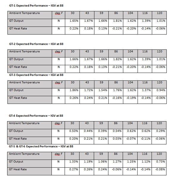
[CE 1.17]
The change of IGV angle on all 6 gas turbines proved to be very valuable in enhancing my engineering experience. This was quite complex project involving multiple teams including design, requisition and application engineering. For each GT; increase in efficiency improved the customer revenue by 50,000 USD per month, total $ 3.6 MM per year for 6 turbines. For GE, this project increased our cash flow by 65000 USD per quarter. I completed the project within the timeline in addition to my everyday tasks. The responsibilities assigned to me included both Technical, Managerial & Administrative aspects. I was the team leader of the tasks but never hesitated to seek guidance either from my senior co-workers or experienced subordinates. This project greatly increased the reliability of the overall power plant and I secured Regional GM Award in category of “Stay Lean to go fast”.
To read complete CDR.............. Kindly check the below links.
We hold the apex position in providing services regarding CDR writing for engineers Australia. We are known to have very high success records for consistent team of professional writers having years of experience in the field of CDR preparation. We provide the best and trusted service for CDR writing and reviewing of all kinds of engineering disciplines. We provide services for career episode writing, plagiarism check and removal etc.
Should you need any further information, please do not hesitate to contact us.
Contact: +61-4-8885-8110
WhatsApp: +61-4-8885-8110
(Australia, USA, UK, UAE, Singapore, New Zealand)