
| Time duration | December 28, 2017 to Jan 2, 2018 |
| Location | Saudi Arabia |
| Organization | General Electric (www.gepower.com) |
| Project | High Vibration on Air Cooled GE 7A6 Generator |
| Position | Senior Manager (Site Manager) |
[CE 2.1]
I joined GE in a Services Leadership Program which was designed to train experienced new hires about GE’s design, operation and financial processes on fast track basis. I had the opportunity to learn and get hands-on experience of maintenance and troubleshooting of several Industrial Gas Turbine ranging from 50MW to 180MW. After completing my one year on job training, I was assigned as Lead Contract Performance Manager to a multi-million dollar long-term maintenance contract with one of prestigious customer i.e. ENGIE. After my hiring I was responsible for preparing computerized maintenance plans, budgeting, coordinating to resolve all technical and contractual issues, executing planned & unplanned outages of assigned power plants. I was also responsible for availability and reliability guarantees of the plants.
[CE 2.2]
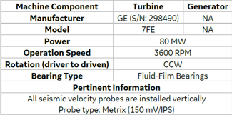
My assigned Power Plant is having 9 x GE Frame 7FA.03 & 2 x 7EA Gas Turbines with the total capacity of 1800 MW. GT2 installed in an oil refinery of Saudi Arabia. The machine train consists of a GE 7E turbine driving a generator running at a design speed of 3600 RPM. Proximity probes are permanently installed at all fluid film bearings of the train to monitor radial vibration levels. Two proximity probes are installed axially on turbine outboard to monitor rotor axial position. The unit underwent a major inspection (MI) where generator rotor was rewound. Comparison of the vibration data before and after MI outage revealed an increase in vibration amplitudes in most of the locations (specifically on the generator). As vibration was on increasing trend so customer was worried. Customer requested me to perform vibration analysis & evaluation of gas turbine along with generator train balancing.
The unit underwent a major inspection (MI) where generator rotor was rewound. Comparison of the vibration data before and after MI outage revealed an increase in vibration amplitudes in most of the locations (specifically on the generator) but they are still well below the alert limit. I decided to start the analyses by ADRE data collection. Onsite data collection was done because seismic vibration data was not available in System 1 Turbine mid-span probe 39VS-21 gap voltage was outside OK limits since May 2017. Data collection from Mark VI was conducted on 31/12/17 and 01/01/18 to capture steady-state, shutdown and cold start-up events.
[CE 2.3]
Main objective of this project was to reduce the vibration values below 15 mm/sec by insitu balancing of generator rotor. This includes 4 phases:
As this was hit & trail method so we anticipated that multiple attempts will be made to solve the issue. In this case it took 7 trials to reach up to required vibration levels.
[CE 2.4]
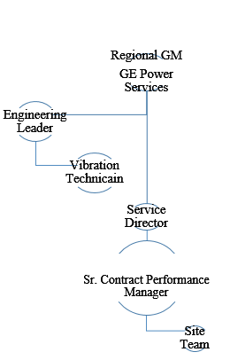
The project Hierarchy is given below. I was responsible to carry out analyses and coordinate meetings with all involved parties. I met field service team who performed last outage on this machine. I came to know that stator rewind was carried also out on generator so I also carried out review meetings with workshop team as well.
[CE 2.5]
I worked as Site Manager on this project. Some of tasks I performed were:
[CE 2.6]
During balance correction, data gathered while trial runs I used two different ADRE units.The X-Y readings indicated swapped probes which meant that ADRE units were hooked up in wrong orientation.
Resulted in incorrect assessment and 1 day of delay
The proper labeling cable was not made for ADRE data cables. Technician didn’t install correctly.
I performed 3 actions to resolve this issue:
While installing balance weights I found cracked balance weight stake marks.
These cracks have the potential to propagate due to continuous cyclic loading at high temperature. Crack propagation increases the risk of material liberation during operation which can lead to hardware damage downstream in the flow path.
Crack initiation in stake marks were due to tensile overload during the staking process residual stresses & stress concentrations.
All cracked stake marks were removed by the following steps.
I analyzed slow roll data at hot and cold conditions and found that there were insignificant differences. However, turbine and generator rotors both had high direct runout values. Slow roll 1X-filtered values were negligible when compared to direct ones which were mainly caused by rotor scratches and surface roughness. The scratches readings were superimposed onto rotor vibrations at the entire speed range of the machine. I decided to polish the rotor journal to remove this run out. For this surface polishing there was no tool available. I designed a small lathe machine and a fixture. I brought portable lathe machine and attached it with circular fixture. I made a travel track of the machine. In this way I could polish the rotor journal area without rotating the rotor. This helped me in getting actual unbalance weight. Rotor journal area polishing was done to meet API standard 670.
[CE 2.8]
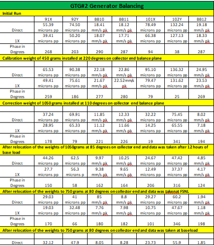
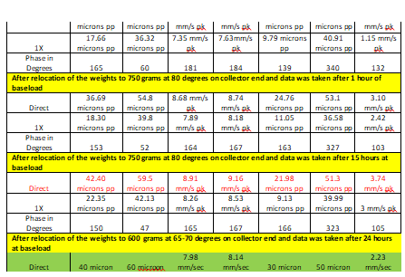
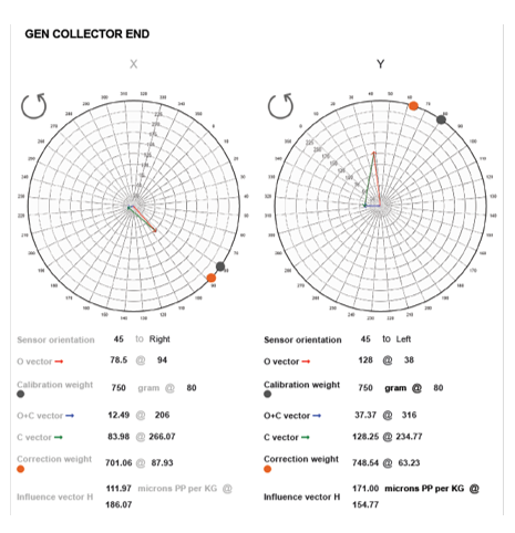
I performed the calculation to get trial weight. I used the formulae: Cf = m r 2 Here: Cf is centrifugal force in LBf (which basically is the output we want to achieve using balance weight) m = Mass of the rotor = Weight (G)/Gravity(G) = Lb/386.4 in/sec2 r = Weight add radius in inches = Rotor speed in radians 1st I calculated trial weight to generate a force equal to 10% of the rotor weight. Secondly I added weight at a 8” radius Later I calculated the speed of the rotor in radians With all above values I could get mass of the rotor. Now, m = W/G, W = m * G In similar way I calculated the weight in every attempt and keep repeating the same till I got required vibration levels. Please refer to below Appendix-2 for detail off each attempt, graphical representation and conclusion.
[CE 2.9]
I recommended and executed following actions after my analyses:
This job significantly increased my understanding on onsite balancing of such hugely unbalanced rotor. Usually it takes 3-4 attempts but this job was completed in eight balance shots/attempts. Main reason was that generator rotor was completely overhauled/rewind however since it was done implying same copper so as per workshop SOP, shop balancing was not required. I suggested the shop team to change the work instruction and perform balancing in the workshop for such jobs as this can be done quite easily and quickly in the shop.