
| Time duration | March 2013 to April 2013 |
| Location | United Kingdom |
| Organization | Anglia Ruskin University |
| Project | Structural Design brief of a School Building |
| Position | Civil Engineer |
[CE 1.1]
This career episode narrates to my project titled “Structural Design brief of a School Building’’. This project was carried out during my tenure at Anglia Rustin University as a Civil Engineer.
[CE 1.2]
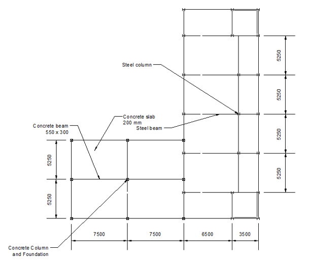
The main purpose of the report was to interpret and understand a client's report that included the construction of a school with steel framing and contiguous assembly and a reinforced concrete dining room. A proposed system and an alternative system that provided the best solution to key issues was selected. In addition, key matters that could affect construction have also been identified.
The report critically evaluated two alternative schemes, in particular aesthetics, function, structural form, structural design, stability, construction methods and economics. To clearly demonstrate the design of the structure, sufficient plans and details of the cross-section were illustrated.
[CE 1.3]
The purpose of this report was to harvest a structural design that provides an adequate, safe and occupant-friendly envelope, as well as the proper transfer of all goods safely to the ground, while respecting the client's report.
The prime objectives were -
[CE 1.4]
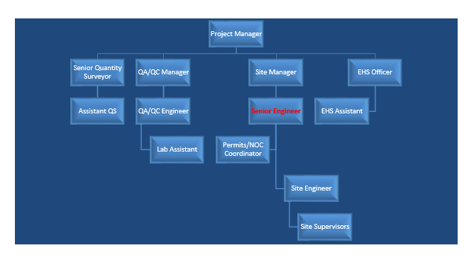
The project Hierarchy is given below -
[CE 1.5]
[CE 1.6]
Access to the site was considered, since the planned road route must be obtained in coordination with the planning regulators. Although it is said that the ground is fairly flat, the planned or already designed levels of this route must be obtained to plan the elevation of the floor level of the building at the design stage.
The site cleanup will commence from the beginning of the route to the site location to create (temporary) access and, depending on the nature of the soil, gravel (hard core) will be required in the road access for ease of movement. Of the site, especially during wet seasons.
Other factors that should be considered during the construction phase would enhance site security and possibly temporary electricity. The current soil was very hard clay. This type of soil was suitable for surface and piled foundations.
[CE 1.7]
Design proposals were given to the authorities by me in order to produce a design for the construction of a school building with offices and adjoining assembly and dining area block including the loading combination design, Floor Plan, Beam Design and Column Design.
I did the Load calculations to ascertain the design strength for the Composite beam, Design and Sizing of the column and others.
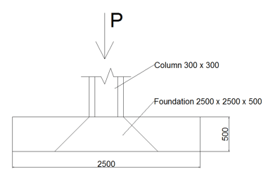
I did following calculations -
Size of concrete column = 300 x 300 = 9*104 mm2
Total maximum load on the column = 940 kN = 940 * 103 N – from column design data
Assume Safe baring pressure = 160 kN/ m2
Assume
Fcu = 40 N/mm2
Fy = 460 N/ mm2
Assume footing weight = 100 kN
So provide s 2.5 m x 2.5 m square base (plan area = 6.25 m2)
Assume the overall depth of footings = 500 mm = 0.5 m
Self-Weight of Footing = 2.52 * 0.50 * 25 = 31.5 kN
Self-Weight of Footing = 31.5 kN > assumed Footing weight = 160 kN need to recalculate plan are of base:

Nominal cover, cnom
cnom = cmin + Δcdev
Assume 12 mm main bars
cmin,dur = minimum cover due to environmental conditions
Assuming XC3 and using C40 concrete,
cmin,dur = 20 mm
Δcdev = allowance in design for deviation assuming no measurement of cover
Δcdev = 10 mm
cnom = 20 + 10 = 30 mm
Check adequacy of section for 2 hour fire resistance (REI 120)
Thickness, hs,min = 120 mm
h =200 mm proposed
amin = 40 mm
a=30+1/2∅=30+1/2 12=36 mm<="" p="" style="box-sizing: border-box; outline: 0px !important;">
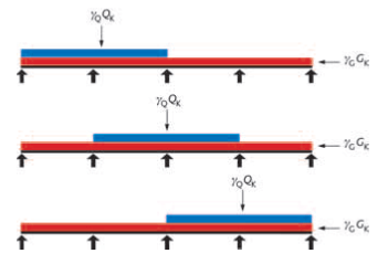
Load combination, Ultimate load, n
1.35Gk + 1.5 Qk
w=1.35*5.5+1.5*4.0=13.425 kN/m^2
Moment at the span AB - M=(wl^2)/8=(13.425*〖5.25〗^2)/8=46.25 kN.m^2
Shear force at the span AB - V=wl/2=(13.425*5.25)/2=35.24 kN.m^m
Effective depth, d
d=h-a =200-40=160 mm
Relative flexural stress, K
K=M_Ed/(b*d^2*f_ck )=(46.25*〖10〗^6)/(1000*〖160〗^2*40)=0.045
K’ = 0.207
z=d/2 (1+√(1-3.53*K))=160/2 (1+√(1-3.53*0.045))≤0.95 d
z=154>0.95*160=152
z=152 mm
Area of steel, As
A_S=M_Ed/(f_yd z)=(46.25*〖10〗^6)/(435*152)=700 mm^2/m
Try H12@150 (AS = 754 mm2/m)
A_(s,min)=(0.26*f_ctm*b_t*d)/f_yk ≥0.0013b_t d=0.0013*1000*135=175.5=(0.26*3.5*1000*135)/500=246 mm^2/m
A_(s,min)< p="" style="box-sizing: border-box; outline: 0px !important;"><>
A_(s,max)=0.04 A_c=0.04*1000*200=8000 mm^2/m
A_(s,max)>A_s OK!
Design shear force - v_Ed≤v_(Rd,c) - concrete shear stress capacity
ρ_1=A_s/(b*d)
Assuming 50% curtailment at the end support, so A_s=700/2=350 mm^2/m,
ρ_1=350/(1000*135)*100%=0.25 %
v_(Rd,c)=0.55
v_Ed=V_Ed/(b*d)=(35.24*〖10〗^3)/(1000*160)=0.22
Percentage of tension reinforcement, ρ_1=A_(s,req)/(b*d)=700/(1000*165)*100%=0.42%
Basic l/d=34
F1 = 1.0
F2 = 1.0
F3=310/σ_s =310/207.5=1.49
σ_s=σ_su (A_(s,req)/A_(s,prov) )(1/δ)=220*(700/742)*(1/1)=207.5 MPa
According Figure 4 [2], σ_su=220 Mpa, because
G_k/Q_k =5.5/4.0≈1.4, ψ_2=0.3 and γ_G=1.35
Basic l/d *F1*F2*F3 ≥ Actual l/d
34*1*1*1.49=50.7>5250/160=33
[CE 1.8]
LUSAS was used for the structural Designing -
[CE 1.9]
Handling the resources was the biggest task for me as every gang had a separate set of fleets working in different locations. I had to ensure to get the required productivity from each machine for which I adopted resource levelling and resource smoothening techniques, which resulted in proper utilization of the material.
Upon observing the whole process of work for all areas of the project and considering the critical issues I had proposed a truck calculation program which will give us the exact number of trucks to complete a particular job taking into account all the external and internal factors like road closure timings, speed of the road, working hours, capacity of the trucks, time to load and off load the material at site, time of travel, waiting time at plant etc.
This was very helpful in deciding the fleet required to carry out the work. Our company standardized this and implemented in all the other projects in our division.
I strictly followed all the relevant Engineering codes i.e. UKB, UKC and EUROCODES. Recommended loading combination from EUROCODE was as following
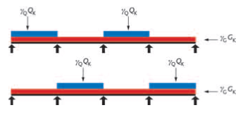
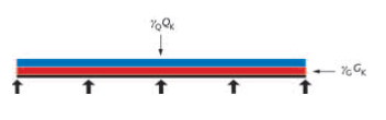
[CE 1.10]
I prepared Bar charts and pie charts to track and monitor the work and show the percentage of completion. I also drafted the cost report sheets for analyzing the internal cost incurred by the company to complete the work and the figures were used by the estimation department for preparing the tender estimate for the future projects.
[CE 1.11]
Project was successfully completed and my working professionalism was highly appreciated at all levels. I completed understood the client requirement after doing some prerequisite analysis of the intended building design. I kept all the aesthetics in line with customers’ expectations. I did numerous calculations in this project and all of them gave me a new perspective of applying theoretical approach on to real life workings.
We hold the apex position in providing services regarding CDR writing for engineers Australia. We are known to have very high success records for consistent team of professional writers having years of experience in the field of CDR preparation. We provide the best and trusted service for CDR writing and reviewing of all kinds of engineering disciplines. We provide services for career episode writing, plagiarism check and removal etc.
Should you need any further information, please do not hesitate to contact us.
Contact: +61-4-8885-8110
WhatsApp: +61-4-8885-8110
(Australia, USA, UK, UAE, Singapore, New Zealand)