
| Time duration | June 2014 to June 2015 |
| Location | |
| Organization | Ford Motor Company |
| Project | Fox Cylinder Head with Spring Seat Surface Damage |
| Position | Quality Specialist & Ford Production System Coordinator |
[CE1.1]
This career episode links to project titled “Fox Cylinder Head with Spring Seat Surface Damage’’. This project was carried out during my tenure at Ford Motor Company as an Industrial Engineer.
[CE 1.2]
There were complaints being lodged regularly from the Engine Sub-assembly area about the cylinder heads being received periodically with damages in the spring seat surface. The part was coming from the head machining department. The machining team knew about the issue that it was related to the aluminum chips being pressed against the surface during Operation 80 – seat and guide assembly. Due to the inefficient cleaning of the head before Seat & Guide press; the aluminum chips from OP.50 (CNC Machining) were not entirely removed at OP.70 (washer), moving towards the spring seat surfaces during OP.80 (press machine) thus causing marks/damages in the surface. This issue upsurge the engine oil consumption & manufacturing rejections.
[CE 1.3]
The scope of this project was to improve the process between OP.50 and OP.80 with focus on reducing 90% of damaged heads and eliminating current ICA (Interim Containment Actions).
[CE 1.4]
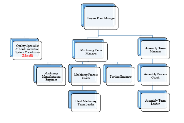
The project Hierarchy is given below. I was answerable to the Engine Plant Manager -
[CE 1.5]
I was responsible for the management of the whole scenario. I drafted all the required documentation of the project & made it possible to have a seamless synchronization amid departments. I also took care of all the project documentation.
[CE 1.6]
[CE 1.7]
The 1st & foremost difficulty was how to identify & remove the chips completely before going to the press operation. So I started my investigation of the design. The investigation sorted the possible route cause which was low quality design of the entire cleaning process (hard to remove chips).
By cutting the cylinder head in pieces, it was possible to see that its design had many cavities/galleries. These narrow areas were hard to conquer with water/air in the intermediate washing system. Also, it was possible to identify that between all the cavities/galleries of the cylinder head some of them had more impact on chips going to the spring seat area, such as the area related to oil return galleries.
By cutting the cylinder head in many different positions, it was possible to see that exhaust side was the most critical region. Due to less oil return galleries it was much more difficult to drain water and chips.
[CE 1.8]
I collected data from measurement phase which was based on 669 defects of spring seat damages. I noticed that exhaust side of the cylinder head was responsible for more than 70% (478) of the spring seat damages. Intake side was less than 30% (191).
In another analysis I divided exhaust side by spring seat number/position, with exhaust 1 & 2 a little bit better due to being closer to the oil return gallery.
I concluded from this 1st investigation that cylinder head design is a strong contributor for spring seat surface damaged due to chips pressed on this surface. Exhaust side was more impacted due to few oil return galleries in its design, but there was no big difference between each spring seat number/position from the exhaust side.
Although the design was a major contributor bu its nearly impossible to change it since this will demand huge time and investment. So I kept it as an opportunity to be studied by the Product Development team for the next Engine Project.
[CE 1.9]
My 2nd investigation refers to a pack of potential causes from OP50 machining. It was basically related to the generation of chips during the machining process, involving chips size, form, quantity, length, etc. Prime point was to verify if current chip generation in each machine is according to initial plan, if it is so then are current chips size, form, quantity, length from OP 50 machining was effective to be removed by OP 70 intermediate washer?
I did comparison between all four CNC machines from OP 50, with an amount of 63 defective parts in 3 days production; I observed that no significant difference was found. First conclusion I made was that it was not an specific machine issue but this could be a process issue affecting all four machines:
I continued investigation on OP 50 process with in the specific region that had excessive impacts on chips going to the spring seat surface. There were several machining operations, some of them were mandatory for OP 50 & some were optional.
All were generating chips in a critical region:
[CE 1.10]
In order to reduce the amount of chips in this region; helping the OP70 washers I moved the optional features (3 & 4) to other machining operations after seat & guide press machines (OP80).
The mandatory features for OP50 (1 & 2) could not be moved, so actions to reduce/improve chips form, size, length, etc, might be required for the related tools. I worked with the tool supplier on tooling design and machining parameters.
[CE 1.11]
During machining of both tools T05002 (tappet bores) and T05004 (spring seat) in order to avoid chips being going to the fixture of the machine I placed the cylinder head up side-down. I did the same when machining exhaust side features since OP.70 Intermediate Washer wasn’t capable to remove chips competently. Later on in OP80 Seat & Guide press machine the machine fixture was of standard design for folding the part in the opposite position:
[CE 1.12]
From the investigation #2 I concluded following -
[CE 1.13]
While carrying out investigation for the capacity of the OP70 HMM-UK intermediate washers in order to assure proper cleaning for OP80 Seat & Guide press machines; I started looking for benchmarks. Process in Cologne Engine Plat (Germany) showed same wash inefficiency. Implying different washer design (rotary washer), but also from HMM-UK, requiring 100% of cleaning being made manually by the operator in order to contain pressing fails. So different washers perofrmed same process but had same cleaning issues. I concluded that it was not a maintenance issue from a specific machine rather it was a design issue of the process.
Even with water jets conquring from everywhere inside the machine I was still hard to achieve the critical region with pressurized water. So it was nearly impossible to remove big size and the amount of chips during the washing cycle.
[CE 1.14]
I took following improvement Actions:
Target: Reduce size of chips
Implemented successfully.
[CE 1.15]
I lead the project from front and confronted any issue professionally. I drafted all the relevant documentation, presentations and reports. I was also liable to present project progress to the company executives. I also compiled the project feasibility study and my report was accepted by the company executives.
[CE 1.16]
Prime target was to avoid residual chips to go into exhaust side galleries, then later dropping down to the spring seat area during Seat & Guide assembly.
I implemented the project with success - Now chips accumulate on intake side of the galleries. Even with chips on the intake side, intermediate washers still have high potential not to remove all chips after washing. However, chips not removed by the washer, now are already down therefore they are not dropping onto spring seat surface. Also, internal area of intake side has 4 oil return galleries, which makes it easier to clean. As a final result, the quantity of rejections on the sub-assembly was reduced from 15% to 3%.
The project gave upsurge to my professional project management topology and my ability to use all types of resources in resolving issues accordingly. The project as a whole elevated my professional existence in all manners.
We hold the apex position in providing services regarding CDR writing for engineers Australia. We are known to have very high success records for consistent team of professional writers having years of experience in the field of CDR preparation. We provide the best and trusted service for CDR writing and reviewing of all kinds of engineering disciplines. We provide services for career episode writing, plagiarism check and removal etc.
Should you need any further information, please do not hesitate to contact us.
Contact: +61-4-8885-8110
WhatsApp: +61-4-8885-8110
(Australia, USA, UK, UAE, Singapore, New Zealand)