
| Time duration | July 2010 to July 2011 |
| Location | Islamabad, Pakistan |
| Organization | Centre for Advanced Research in Engineering (CARE) Centre for Advanced Studies in Engineering (CASE) |
| Project | Wireless Control of Single Phase AC Motor Speed with High Precision |
| Position | Team Leader / Senior Research Student |
This career episode is about my project named “Wireless Control of Single Phase AC motor Speed with High Precision”.
[CE 3.1]
Center for Advanced Studies in Engineering (CASE) was established in 2001 with the main campus situated in the heart of Islamabad in G-5 / 1 sector Pakistan. CASE provides its students state of the art educational facilities with highly qualified faculty from USA and rest of the world. CASE has established its own research center to enable engineering students to work along with researchers, and scientists to attain practical knowledge in research & development sector, which is known as CARE (Center for advanced Research in Engineering).
www.case.edu.pk
www.carepvtltd.com
[CE 3.2]
I worked as a Senior Research Student / Team Lead to assist my junior batch in completion of their Final Year Project, I was accompanied by two of my project fellows Engr. Mahfoz & Engr. Farhan during year 2010 – 2011, our focus was to design an embedded system based project, so after extensive research and brain storming we have chosen” Wireless Control Of Single Phase AC Motor Speed With High Precision” from the available list of projects which were available to the final year students under various Phd Qualified Faculty Members. The project was supervised by Senior Faculty Member of CASE Dr. Saeed ur Rehman.
A technology commonly known as wireless control is being implemented to control various devices and home appliances such as TV, AC etc. Taking this basic concept, I implemented the wireless control technology on” SINGLE PHASE AC MOTORS”. Controlling the motor speed through remote control, have many applications like we can control the speed of fan or desert cooler or the water pump motor of the fountain and so on.
[CE 3.3]
The project aims to assists domestic & industrial consumers to control SINGLE PHASE AC MOTOR equipment such as (Fans, Air Coolers and Water Pumps) with a speed variation ranging from (1 – 99) since the appliances available in market have been offering only three modes of speed operations (Low, Medium and High) and usually implemented in DC Systems. Our project facilitated the consumer to adjust the speed control as per their requirement. Similarly, same system is appropriate for governing lighting intensity.
In this project I have controlled the speed of single phase AC motor with the aid of remote control with high precision. High precision means that speed will upsurge or decrease not only in one or two steps but in quantity of steps (100 steps).
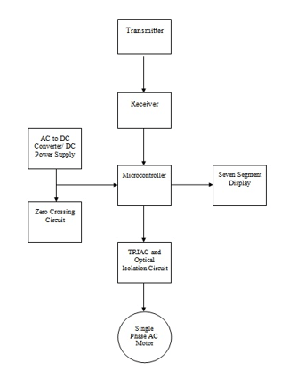
As I controlled the speed through remote control I used microcontroller to decode the pulses produced by the remote control so that action was taken accordingly. Our project mainly comprises of three parts Power Electronics, Embedded Systems and Wireless Control.
[CE 3.4]
The hierarchy for the project is displayed below -
[CE 3.5]
[CE 3.6]
During the hardware design and testing, the electronic components got damaged as reversed voltage was applied to the circuitry by one of the team member. As per my previous design experience I emphasized the students to design the built-in power supply for all the electronic circuitry and designs. The external power supply can be used during initial stages for the result verifications however it has always been the best practice amongst the professionals to design & execute power supply within the circuitry for easy trouble shooting, all the electronic components can be effortlessly checked. I implemented Reverse voltage protection in the power supply by adding a diode in the negative Terminal of the power supply so that none of the IC could be demerged if the reveres voltage is applied accidently.
Previously the seven-segment display want the part of our project. Later I noticed that without the display our project doesn’t full fill the requirements even though the speed variation was staking place while using a remote control. However, it has been the best idea in order to let the user see how much speed adjustment he has made starting from 1 to 99 which will add up more to the project therefore I programmed seven segment displays and added to the hardware in order to see the real time speed verification.
Main problem we faced while using various type of remote control existing in the market, most of the waveform I checked using receiver circuit gave us distorted waveform which was very firm to detect. Therefore, I kept the focus over using only 2 kinds of remote control offered in the marketplace.
The soul of our project was wireless control of single phase A.C motor speed. Phillips and Sony remote control was used as transmitter and simple IR receiver was used on the receiver side. Four buttons (1, 2, 3 and 4) of Phillips remote control and Sony remote control were used to execute four commands namely Speed Up, Speed Down, Off and On/Normal Speed.

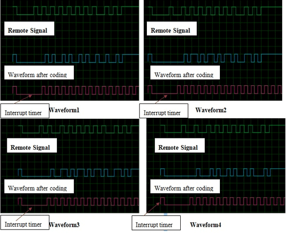
My job here was to decode the receiving waveforms at the demodulator output. I observed the direction of the changing at the middle of the bit, if going down, means bit 0, going up, means bit 1. But it was easy to sample the middle of the first half of the bit, so it directly tells us what the bit state is. I was decoding the pulses through Manchester scheme because Phillips remote control was using RC5 protocol and Manchester was the decoding scheme.
In the Philips remotes, the bit #3 is the CHECK bit, every time you press a key at the remote, even pressing repeatedly the same key, this bit flips state.
[CE 3.7]
Decoding the IR transmitter waveform:
I used SONY remote control and PHILLIPS remote control to change the speed of the single-phase AC motor speed. By using two different remote controls, added diversity in our code.
Decoding Sony remote control waveform:
[CE 3.8]
The power supply which was the main component of our design, since we must use various voltage levels to energize our circuit therefore we were sing two different power sources, which has made our circuit bulky and not easy to carry. Therefore, I came up with an idea to implement the DC power supply within our same circuit.
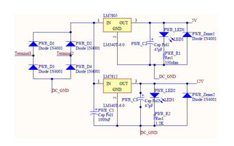
There are numerous components in our circuit those require 5V and 12V for their proper functioning, so for that purpose I have developed power supply circuit to supply DC voltages of 5V and 12V to those components. The schematic of power supply circuit made on PROTEL is shown below
I have designed & implemented the Zero- crossing detector which is an applied application of comparator. Zero- crossing detector using inverting op-amp comparator is depicted in above figure.
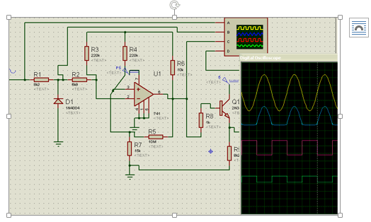
As shown in above figure the first wave (sinusoidal wave) is the input to the ZCR with amplitude of +12V and -12V. The second wave shown in above figure is the one rectified and negative part of the input signal is removed due to rectification. The third pulse, the square wave is the output of the op-amp and its peak to peak amplitude is 12V, this signal cannot be directly fed into the microcontroller, so the amplitude is reduced to 5V by passing it through transistor 2N3904 and this is shown in above figure.
[CE 3.9]
Hardware testing has been performed by me after soldering all the electronics components over the PCB (Printed Circuit Board). The Power Supply has been re-checked by using MultiMate (DC Voltage Measurement), there were some distortion has been found in the power supply due to over hatching of the copper layers in the single layered PCB Board, the problem was solved by soldering all the distorted tracks one by one.
The output wave form from the circuits has been checked by using oscilloscopes corrective measure has been taking in the hardware to avoid any problem.Software issues have been resolved by me. The code programmed in to micro-controller was very sophisticated and very hard to trouble shoot during the project execution stage. Therefore, I have segregated and gave title to each component of the using Call functions in order to correctly identify each problem to attain the desired goals. For example, the following code has been separated for the Seven Segment Display:
///////////////////***** DECIMAL 2 BCD CONVERSION FUNCTION *****/////////////////// void dec2BCD (unsigned int dec) { unsigned char w,z; unsigned char bcdbyte; w=dec/10; z=dec%10; w=w&0x0F; w=w<<4; z=z&0x0F; bcdbyte =w|z; P1=bcdbyte; }
[CE 3.10]
TRIAC was connected to MOC3023 on one side and the inductive load on the supplementary side. We were implementing the dimmer circuit, but the variance is that in dimmer circuits DIAC was used to trigger the TRIAC but here we are implying microcontroller to trigger the TRIAC. Our project goal to variate the speed from 1 to 100 and this task is attained by creating pulses of different widths which are fed into pin 2 of MOC3023. The TRIAC is synchronized to the input AC power signal through zero crossing circuit. The task to increase speed of single phase AC motor by one step through 1 to 100 was achieved by following steps. f= 50 Hz, T=1/50=20ms 20ms/2=10 ms %for half wave 10ms/99=101microsec %dividing into 99 parts This means that variance amid two steps is 101 micro seconds.
[CE 3.11]
I worked on following things udring this project -
[CE 3.12]
As there were many areas where works were going on simultaneously every day I was interacting with my team members to discuss regarding the targets to be achieved, scope of the work, resource allocation and design implementation. Weekly meetings have been scheduled to narrate the project progress and brief issues to the project supervisor. Different techniques & approaches had been discussed during each session. Coordination and meetings has been carried out with different faculty members for the project I have excellent communication, Technical &problem-solving skills which has aided me to Lead this Project and therefore all my decisions and command has been followed and appreciated my squad associates & supervisors. accomplishments.
[CE 3.13]
Project was completed and tested successfully it earned me much appreciation from my supervisor and projected my confidence to work anything out in embedded system design and implementation’s. Starting from a simple idea and giving it an operational look has enhanced my confidence in research and development sector.
I worked as a Team Leader due to my previous knowledge in the design project and as a senior to my junior batch fellows and assisted team members in terms of circuit design, testing and troubleshooting.
My task included supervising the whole projects to make sure that all the things are going in the right direction and to complete the project within the given span of time. I assisted the team in preparing reports, arranging meetings and giving presentations involved with the stages of the project, updating project progress aiming towards the final execution.
Learning’s from the project are as below -
To read more.............. Kindly check the below links.
We hold the apex position in providing services regarding CDR writing for engineers Australia. We are known to have very high success records for consistent team of professional writers having years of experience in the field of CDR preparation. We provide the best and trusted service for CDR writing and reviewing of all kinds of engineering disciplines. We provide services for career episode writing, plagiarism check and removal etc.
Should you need any further information, please do not hesitate to contact us.
Contact: +61-4-8885-8110
WhatsApp: +61-4-8885-8110
(Australia, USA, UK, UAE, Singapore, New Zealand)