| Date of Start of Project | 23rd February 2017 |
| Date of Completion of Project | 1st May 2017 |
| Location of the Project | Jalandhar, Punjab |
| Organization | |
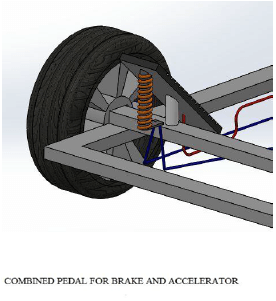
| Project Name | Combined Pedal for Brake & Accelerator |
| Designation & Role | Mechanical Engineer, Calculation of forces & stress analysis in break |
[CE 1.1]
This career episode narrates to my project bearing title “Combined Pedal for Brake & Accelerator’’. This project was carried out to fulfill the requirement of Mechanical Engineering Degree completion.
[CE 1.2]
During braking, the foot pedal and support both moves in full downward direction such that, there would be no acceleration of the vehicle. This is achieved by fixing the acceleration cable at the bottom end of the pedal near the heel rest. The braking will be achieved by pressing the foot pedal fully down, to get the original position the spring is attached between pedal and the support. On releasing the pedal, the spring tends to come in original position due to spring action. Hence the driver can able to operate the vehicle using a single pedal.
[CE 1.3]
During acceleration, the foot pedal rotates about the downward direction and lower half of pedal moves in upward direction i.e. rotation of foot pedal would be in anticlockwise direction. The support is kept below the foot pedal during acceleration, this opposite force is done by using helical spring. The main purpose of spring is to provide Resisting force to the support during throttling. Hence, by using upper half of the foot, driver can accelerate the vehicle without actuation of brakes.
[CE 1.4]
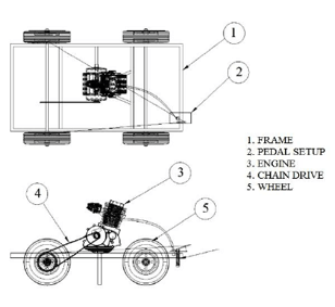
I completed this project in congregation with TWO other engineers. I was given the chance to lead the team.
The project Hierarchy is given below.
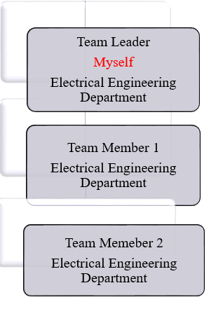
[CE 1.5]
I did the project handling and management of this academic project since I was chosen team leader. I first consulted and discussed the entire project with my team mates and finalized to break down the project into multiple milestones and execute using this topology of management. I allocated multiple tasks to each member. After completion of each milestone I prepared a report and discussed the same with our project supervisor. I managed all the issues professionally and resolved in consent with the project supervisor.
[CE 1.6]
I went through all possible source to have an indepth understanding of the project working. I first gathered some information from the boks available in our university main library. I also chunked some piece of information from the internet.
[CE 1.7]
My Roles & Responsibilities -
[CE 1.8]
During acceleration, the foot pedal rotates about the downward direction and lower half of pedal moves in upward direction i.e. rotation of foot pedal would be in anticlockwise direction. I kept the support below the foot pedal during acceleration, this opposite force is done by using helical spring. The main purpose of spring is to provide Resisting force to the support during throttling. Hence, by using upper half of the foot, driver can accelerate the vehicle without actuation of brakes.
During braking, the foot pedal and support both moves in full downward direction such that, there would be no acceleration of the vehicle. I achieved this by fixing the acceleration cable at the bottom end of the pedal near the heel rest. The braking will be achieved by pressing the foot pedal fully down, to get the original position the spring is attached between pedal and the support. On releasing the pedal, the spring tends to come in original position due to spring action. Hence the driver can able to operate the vehicle using a single pedal.
[CE 1.9]
As a team leader I drafted the list of components and the fabrication procedure for the combines pedal mechanism.
Components Used -
I played key role in fabrication. The C40 steel square-section is cut into two or more pieces to the required size of the material. Then I assembled it to make the chase frame. The welding process was carried out. Before finishing welding the structure, I verified whether the structure is in right angle or not. I used L-angle to make support stand for fuel tank and engine. I connected the four wheels to the chase frame. The engine was mounted on the chase frame and bolted for the support. Then I connected the acceleration cable to the lower end of the foot pedal. The foot pedal is a 3mm metal plate which was supported on the column. After that I connected the brake line from two wheels are connected to the support column.
[CE 1.10]
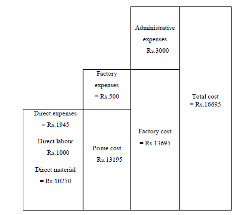
I did the cost estimation after some thorough market research in congregation with the team mates. The details are as following
Length (l) = 1200 mm Breadth(b) = 600 mm Width(w) = 300 mm Volume of frame = 2(l xbxw) Volume of frame (v) = 43.3x106 mm3 Total volume = 43.3x106 mm3 Total weight = 43.3 x 103 x 7.8 x10-6 Total weight = 38.9 Kg Total material cost = Total weight X Cost of material per kg Total material cost = 38.9 x 50 Total material cost = Rs.1945 Overall material cost = Rs.1945
Cost of engine = Rs.5000 Cost of wheel = Rs.3600 Cost of bearing = Rs.800 Cost of chain and sprocket = Rs.600 Cost of accelerator and brake cable = Rs.250 Overall cost expenses = Cost of engine + Cost of wheel + Cost of bearing + Cost of chain and sprocket + Cost of accelerator and brake cable Overall cost expenses = 5000 + 3600 + 800 + 600 + 250 Overall cost expenses = Rs.10250
Charges of welding = Rs.700 Charges of cutting = Rs.300 Overall direct labour cost = Charges of welding + Charges of cutting Overall direct labour cost = 700+300 Overall direct labour cost = Rs.1000 Prime cost = Direct material cost + Direct expenses + Direct labour cost Prime cost = 1945 + 10250 + 1000 = Rs.13195
Cost of paint and brush = Rs.500 Overall factory expenses = Rs.500 Factory cost = Prime cost + Factory expenses Factory cost = 13195 + 500 Factory cost = Rs.13695
Charges for binding records = Rs.3000 Overall administrative expensive = Rs.3000 Manufacturing cost = Factory cost + Administrative expenses Manufacturing cost = 13695 + 3000 Manufacturing cost = Rs.16695 Total cost = Rs.16695
I also assimilated the Ladder of Cost as following -
[CE 1.11]
I prepared the 2D & 3D drawings of the project prototype as following.
Front View
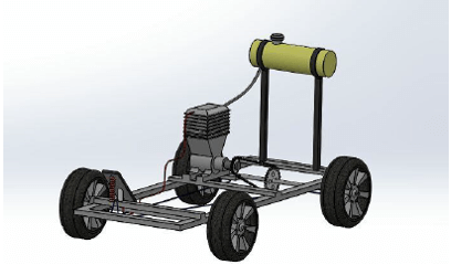
Side View
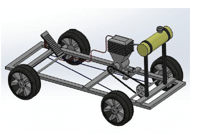
Pedal View
2D View
[CE 1.12]
I used my collective knowledge of design calculations to rectify numerous calculation issues during this project development.
Foot Pedal: Material: MS Steel Length: 175 mm Width: 101 mm Thickness: 4 mm Weight: 300 g The foot pedal rests at an angle of 45 Design of Bolt: Material: C20 steel Yield stress τ: 260 N/mm2 Pressure: 1.2 N/mm2 Length: 200 mm Thickness: 15 mm No of Bolts: 4 Total load, P = A x p = 200 x 15 x 1.2 = 3600 N It is shared by 4bolts, P = 3600 / 4 P = 900 N (load acting on one bolt) Stress area = [ 60 P / τ] (2/3) = [ (60 x 900) / 260] (2/3) Stress area = 35.07 mm2 For stress area = 35.07 mm2 [from PSGDB 5.42] I choose M 6 bolts Design Calculation of Chain Driver Power P=0.1KW Speed N1=1500rpm Speed N2=1000rpm Centre of distance (ao)=600mm Determination of the Transmission Ration: Transmission ratio i = (N1/N2) = (1500/1000) i = 1.5 Selection of Number of Teeth on the Driven Sprocket (Z1): Range of i = 1-2 Z1=27 (chosen) Determination of Number of Teeth on the Driven Sprocket(Z2): Z2 = i*Z1 = 1.5 * 27 Z2= 41 Calculation of Length of Chain I computed the length of chain as following Number of link lp= 2ap+((z1+z2)/2))+[(z2-z1)/2π)]2/ap] ap = ao/p =600/15.875 =37.795 lp = 2(37.795)+((27+41)/2)+[((41-27)/2 π)2/37.785))] =75.59+34=0.1303 =110 links
[CE 1.13]
The project played momentous role in my career. The new technical knowledge I gained was -
The project also raised my project preparation, forecasting, leading & administration skills. I also attained know how of using outside resources when the team was not able to figure out the complicated issues. I also erudite a lot about team management skill. Overall this project played a role of building block in my professional experience.
I played my part as a team lead and did all the necessary project engineering activities being allocated to me. I performed most difficult tasks i.e. 2D and 3D design, engineering design calculations and final project report. My working in this project was endorsed by the project supervisor.
We hold the apex position in providing services regarding CDR writing for engineers Australia. We are known to have very high success records for consistent team of professional writers having years of experience in the field of CDR preparation. We provide the best and trusted service for CDR writing and reviewing of all kinds of engineering disciplines. We provide services for career episode writing, plagiarism check and removal etc.
Should you need any further information, please do not hesitate to contact us.
Contact: +61-4-8885-8110
WhatsApp: +61-4-8885-8110
(Australia, USA, UK, UAE, Singapore, New Zealand)