
| Date of Start of Project | 2nd February 2017 |
| Date of Completion of Project | 5th April 2017 |
| Location of the Project | Chennai, Tamil Nadu, India |
| Organization | St. Joseph’s Institute of Technology |
| Project Name | Fabrication of Elliptic Trammel Tool Changer Model of Robot Arm & Effector |
| Designation & Role | Mechanical Engineer |
[CE 2.1]
This career episode describes my project bearing title “Fabrication of Elliptic Trammel Tool Changer Model of Robot Arm & Effector’’. This project was carried out to fulfill the requirement of Mechanical Engineering Degree completion.
[CE 2.2]
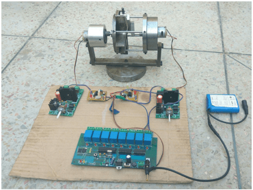
The assembly process having robots at work involves numerous dimensions. Robots can be used in the assembly process to reduce the time lag of the production. Moreover, assembling and dismantling of tools on robot arm by pneumatic tool changing concept also takes time for production. This concept of tool change reduces the time for tool change in assembly and drilling operations of robot arm. This model has four different tools including two sliders consisting of two different tools each within the end effector. This concept works by using stepper motors which are programmed initially to drive as expected by D.C, supply lithium ion battery, controlled by mobile phone Bluetooth by the aid of numerous control boards like Speed control board, Bluetooth control board, Bluetooth controller, Driver board and Timer board. The design is fabricated as to hold one motor which drives the path profile of sliders and other motor is used to drive the sliders using crank. By controlling the angle rotated by shaft of motors, we can change the tool in robot arm end effector and the whole end effector of robot arm will act as a spindle to perform operations.
[CE 2.3]
The main objective of this project was to change the tool within the robot arm end effector using inversion of Double slider crank mechanism i.e. Elliptic Trammel mechanism. This project described the working of Elliptic Trammel mechanism using Stepper motors to perform tool change operation in four directions. I executed the entire system to have its tool change operation by reciprocating motion in both horizontal and vertical direction.
There are four different tools attached at the end of two sliders; each containing two tools and they perform changes within the end effector when the sliders are in motion. The sliders of the mechanism move perpendicular to each other which is driven by stepper motor. The midpoint of connecting component connecting the two sliders traces a circular shape. A crank is made to rotate on the traced path connected to the small pin on the midpoint of the connecting component and crank fixed with the shaft of stepper motor. Stepper motor carrying the crank guided with the eccentric aluminum cylinder for making the axis of shaft to rotate in constant speed while deflecting. When the shaft of stepper motor is rotated, the crank also rotates which in turn gives rotational movement to the connecting component. This rotation helps to reciprocate the sliders in horizontal and vertical pathway which in turn provides a very convenient mechanism for tool change within robot arm end effector.
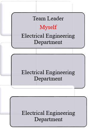
[CE 2.4]
This project was executed in a group of three engineers including me. The hierarchy is displayed below -
[CE 2.5]
I was accountable for the project management as team leader. I resolved all the glitches and snags that arise during the project completion. I allocated the tasks to all the team members. I also kept in synchronization with the project supervisor and gave him details on project proceedings on weekly basis.
[CE 2.6]
I left no stone unturned in finding the already work done in this field. I did both online and offline research to get the best knowledge of the project objectives. I also dicussed the matter with the senior engineers.
[CE 2.7]
I worked as Site Manager on this project. Some of tasks I performed were -
[CE 2.8]
In this fabrication model, change in tool within robot arm end effector was performed by me implying elliptic trammel mechanism i.e., double slider crank mechanism. I mounted the tools in cross section of two sliders which were connected with each other using connecting component. When the sliders move along the path profile, which was connected via connecting component, the center of the connecting component traces circular path. I mounted a pin on the center of connecting component; a crank was connected with one end at the center of connecting component and other end with fixed shaft of stepper motor. Thus, by controlling the step angle of 90ͦ of stepper motor shaft, sliders move to the other end of path profile. The tool can completely change when it turns to locate in position along with axis of end effector spindle. So, to control the position of path profile I used another stepper motor which has the step angle of 90ͦ.
I controlled the two stepper motors by Bluetooth board, Bluetooth controller, Timer board, Driver board and Speed controller board. The stepper motors were commanded by mobile phone Bluetooth. When the command is given via mobile phone Bluetooth, the Bluetooth controller board receives signal and converts signals to binary value with ‘1’ as start and ‘0’ as stop. From Bluetooth board, the signal passes to timer board which controls the time sequence of command given to stepper motor to rotate the shaft.
[CE 2.9]
I used a Mild steel cylinder to mount the stepper motor already mounted with Aluminum cylinder which holds the crank, connecting component and sliders along with guide cylinder being connected to Path profile. Another stepper motor holds the path profile via shaft and was mounted in Aluminum cylinder. Similarly, I connected all the joints to each other by Allen bolts and grip screw. These two shafts of stepper motors rotate clockwise to transmit power to start tool change process. Hole was drilled by team memeber on the sliders, connecting component, crank, base part, Path profile, guide materials and threaded to create screw thread.
[CE 2.10]
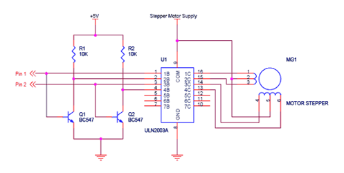
I as a team lead described the Stepper motor connection. There are actually many ways to interface a stepper motor to the controller.
The most used interfaces are -
As seen in the circuit below the four pins "Controller pin 1",2,3 and 4 will control the motion and direction of the stepper motor according to the step sequence programmed in the controller.
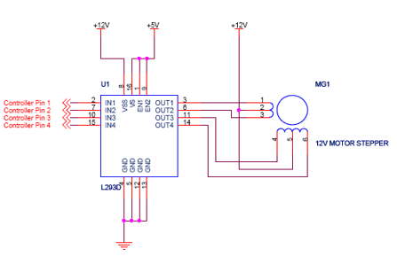
In this circuit four pins "Controller pin 1", 2, 3 and 4 will control the motion and direction of the stepper motor according to the step sequence sent by the controller.
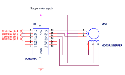
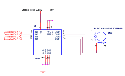
In this case we can simplify the design to make controller use less pins with the help of 2-wire connection method. The circuit for 2-wire connection is shown below.
The bi-polar stepper-motor has similar sequence as that of uni-polar stepper-motors. H_bridge was needed on the driving circuitry since it permits the polarity of the executed power to be driven autonomously. This can be done as shown in the figure below:
This is the methods for connecting stepper motors with a microcontroller.
[CE 2.11]
I used my collective knowledge for programming full strep sequence. My flawless programming played vital role in our project success.
[CE 2.12]
Torque Analysis I carried out this analysis all by myself. Torque of the stepper motor (as specification) = 30 kg-cm = 2.943 N-m Torque due to fabrication = Moment of Inertia x Angular acceleration T = I x α Moment of Inertia I = I1 + I2 +I3 +I4 +I5 Mass Moment of Inertia for Guide 1 for path profile I1 = (m x r x r)/2 = (((π x 95 x 95 x 〖10〗^(-6) x 8 x 〖10〗^(-3))/4) x 7850 x ((95 x 95 x 〖10〗^(-6) ))/(4 x 2))) = 5.0217 x 〖10〗^(-4) kg m^2 Mass Moment of Inertia for Guide 1 for path profile I2 = (m x r x r)/2 = (((π x 95 x 95 x 〖10〗^(-6) x 10 x 〖10〗^(-3))/4) x 7850 x ((95 x 95 x 〖10〗^(-6))/(4 x 2))) = 6.277 x 〖10〗^(-4) kg m^2 Mass Moment of Inertia of Guide 1 for path profile I3 = (m x r x r)/2 = (((π x 54.7 x 54.7 x 〖10〗^(-6) x 25 x 〖10〗^(-3) )/4) x2700 x ((54.7 x 54.7 x 〖10〗^(-6) )/(4 x 2))) = 0.5932 x 〖10〗^(-4) kg m^2 Mass Moment of Inertia for Path profile I4 = Iz = 4 x ((M x((b^2- d^2)/12)) – (M1 x((〖b1〗^2-〖d1〗^2)/12))) =4 x ((0.165 x((〖21〗^2- 〖20〗^2)/12)) – (0.0883 x((〖15〗^2-〖14〗^2)/12))) = 1.4014 kg m^2 Mass Moment of Inertia for Sliders and Connecting component I5 = Iz = 2 x ((M x((b^2- d^2)/12)) – (M1 x((〖b1〗^2-〖d1〗^2)/12))) = 2 x ((0.014 x((〖15〗^2- 〖14〗^2)/12)) – (0.019 x((〖15〗^2-8^2)/12))) = 0.0926 kg m^2 I = I1 + I2 + I3 + I4 +I5 I = 0.00050217 + 0.0006277 + 0.5932 + 1.4014 + 0.0926 I = 1.4952 α = (ω1- ω2)/(t1 -t2 ) = (3.141-0)/(2-0) = 1.57 radians/s^2 T = I x α = 1.4952 x 1.57 = 2.3486 N-m Since the torque of the stepper motor is greater than torque calculated from fabrication i.e. 2.943 > 2.3486. So, the design was safe.
[CE 2.13]
This project work was completed within the limited time successfully. THE FABRICATION OF ELLIPTIC TRAMMEL TOOL CHANGER OF ROBOT ARM END EFFECTOR was working with envisioned topology. The future depends on automation and robotics is essential source for production department. Since time plays a major role in production, tactics for dismantling and assembling of tools makes time delay. By introducing this concept, the time lag can be eradicated. The project work was done to the best of the team members aptitude and talent enduring thoroughgoing use of existing facts. The operating procedure of our designed system was very simple, so any person can operate. By using different techniques, they can be modified and developed according to the needed applications.
We hold the apex position in providing services regarding CDR writing for engineers Australia. We are known to have very high success records for consistent team of professional writers having years of experience in the field of CDR preparation. We provide the best and trusted service for CDR writing and reviewing of all kinds of engineering disciplines. We provide services for career episode writing, plagiarism check and removal etc.
Should you need any further information, please do not hesitate to contact us.
Contact: +61-4-8885-8110
WhatsApp: +61-4-8885-8110
(Australia, USA, UK, UAE, Singapore, New Zealand)