
[CE 2.1]
Project: Smart Energy Meter
Duration: [Date] – [Date]
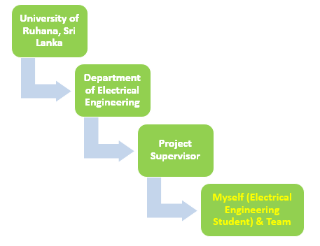
Location: University of Ruhana, Sri Lanka
Position: Electrical Engineering Student
[CE 2.2]
For measuring the energy consumption of any residence, an energy meter is a device which typically used. In past, an energy company typically hires a person for noting meter readings during the preparation of billing on monthly basis. These readings are used for calculation of electricity bill and then it dispatches to the consumer house.
[CE 2.3]
The project aim was a development of the energy meter which was for monitoring, communicating, and storing consumption data with the customer and service provider. It resulted to reduce the manual efforts for taking the readings from the energy meters and implemented a cost-effective solution. I developed a software program that was specifically for maintaining communication and transferring data with the smart control center and customers. I provided the needed data to the customers of the energy utilization throughout a day and it could result in taking mandatory measures for improving and reducing the monthly electricity bill. I split the project into two sections which were software development and hardware development.
[CE 2.4]The work nature was the GSM-based energy meter designing mainly for domestic energy meter controlling. I utilized the GSM technology which resulted in allowing the customer to receive messages regarding the power consumption at each month's end. I implemented the project which assisted in optimum energy management and energy conservation with the appropriate electrical engineering skills implementation.
[CE 2.5]
[CE 2.6]Duties:
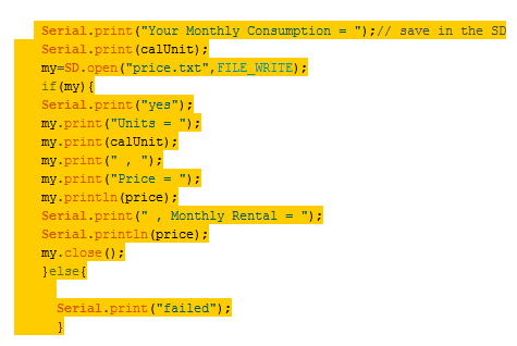
I calculated the power utilized which was stored in the SD card and the storage purpose was based on providing the needed details for the power usage forecasting for upcoming years. I used the communication path in the project for sending the records which were not developed and it was based on executing the design using an Arduino Wi-Fi module along with the data storage cloud.
I used an LCD which indicated the current, voltage, and number of units' real-time values. Thus, the customer was able to analyze the energy consumption at the provided time instant of the day and took mandatory measures for reducing the utility bills.
[CE 2.9]
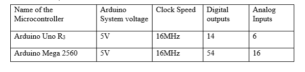
I selected the optimum components for carrying out the designing and it included GSM module, microcontroller, current sensor, LCD, and SD card module. These were the appropriate components utilized in the project and analyzed various aspects of the components selection. I also did the comparison between two microcontrollers which is shown in the table below:
[CE 2.10]
I executed the two measurement blocks in which once acted as the block of voltage measurement and current measurement. I made power supply connection the step-down transformer in the voltage measurement block and the secondary end was associated with the voltage divider circuit. There were two resistors values set for carrying out the operation. The transformer secondary voltage was split into the 10:1 ratio and obtained the voltage across the low-value resistor mainly obtained for the analog pin feeding of the Arduino and the AC signal contained both the positive and negative values. However, the microcontroller was only able to read the positive values and carried out negative values conversion into the positive values. I managed to obtain the DC voltage shift provided to the incoming signal with the 5V DC supplied to the voltage divider circuit. It considered of the two higher values resistance mainly worked in splitting the voltage values and obtained the appropriate DC shift mainly worked with the incoming voltage level. The signal negative portion was converted into the positive sequence as the Arduino was able to read only the positive values. I converted the voltage which was compatible with the Arduino and supplied it to the Arduino analog pin.
[CE 2.11]
I displayed the currents, voltages, and associated consumption of real power with the power factor as well as with the billing information on LCD. I made LCD connection to the Arduino and the measurement of energy was done from multiplication of the real power from the load. All the values were stored in the SD card and the snap action specifically used for obtaining the tampering alert which worked in case if the unauthorized person tried to open the meter casing. I made storage of the tampering information in the SD card along with the GSM module connection to the Arduino from the serial communication pin. Received and transmitter pins mainly associated with the module and these worked with the pin 9 and 10 of the Arduino. I worked on GSM 5V supply from the GSM module and Arduino operated from AT commands. The commands mainly worked with the usage of the controlling and communicating with the GSM modem. These were typically termed as the AT commands and it was successfully associated with the defined functional values.
[CE 2.12]I selected the Arduino Mega 2560 in which analog inputs and digital outputs were higher than Arduino Uno. I utilized more than 6 analog input signals and Arduino Uno was not adequate for supplying the needed inputs. I selected the SIM800L as the GSM module and it was due to its low cost and it fulfilled the requirements. I selected the ACS712 as the current sensor which was available in three different versions. The system designed was embedded with 30A. I used the SD card in the project which needed nearly 5V input voltage for carrying out the operation and the system accordingly operated following all the requirements. I made the system user friendly and enhanced the overall efficiency of the system. The implemented work significantly boosted my Electrical Engineering knowledge in the project.